
voltmeter

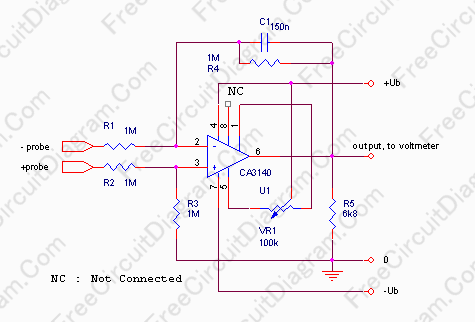
When a low voltage is applied, LED D1 lights up as current flows through it, and resistor R1 acts as a current limiter. Once the voltage applied to the circuit reaches approximately 12V, the Zener diode begins to conduct. The current through the Zener diode causes a voltage drop across resistor R2, which activates transistor T1, effectively cutting off the voltage across LED D1. At this point, no LED is illuminated, which indicates a healthy charging system. If the voltage rises above 14.6V, the voltage drop across resistor R4 becomes sufficient to activate transistor T2, causing LED D2 to light up. While most components are not critical, a few exceptions exist: (1) the value of the Zener diode determines the exact voltage limits, and it is advisable to verify its actual Zener voltage before use; (2) for T2, a higher β allows for an earlier activation of LED D2, necessitating slight adjustments to R4 (for example, using 1.5k for a BC547B or 1.2k for a BC547C). Typically, with the specified values in the circuit diagram, the red LED begins to fade around 12.1V and is completely off at 12.6V. The yellow LED starts to glow at 14.6V and is fully illuminated at 15.0V. Note that resistors R1 and R5 are designed for 20-mA LEDs.
The circuit can be assembled on a small piece of breadboard or a custom PCB. To protect against vibrations, humidity, and dust, the PCB can be encased in a plastic tube and sealed with epoxy resin, with an M6 bolt embedded in the resin for mounting. It is important to note that this setup is very basic; there is no protection against reverse polarity, nor is there a fuse, so it must be connected to a fused line. There are various installation options for this device. One version includes an M6 bolt on its back for versatile mounting. A common method is to use a simple clamp to attach the voltage indicator to the handlebar. On early BMW R80/100GS and G/S models, the device fits well into the clamp at the upper end of the left fork that was intended for BMW's chronometer. Alternatively, zip ties can be used to secure it above the instrument cluster, which has been successfully implemented on many Honda Africa Twin models where access to the necessary electrical connections is straightforward, as well as on Suzuki DR350 motorcycles.Typically, most japanese motorcycles do not have any charge control lamp at all and even on bikes equipped with such a lamp (Bosch system, e. g. BMW and Moto Guzzi), defects may still occur in a manner where the "idiot light" may not light up in due time.
The circuit presented here is a simple means to overcome this problem. The device is used to monitor the battery voltage continuously: As long as this is around 13. 6V ( ± about 0. 8V), the charging system is very probably working properly. The circuit itself is of a rather minimalistic design, with only two LED to indicate the actual voltage range. A red LED is used to signal a voltage that is too low to charge the battery (usually a sign for alternator failure), and a yellow one that indicates overvoltage (usually due to a defective voltage regulator).
Thus, it is more a "voltage indicator" than a "voltmeter". Why only two LED There are many circuits available that use e. g. three, five or more LED to indicate the actual voltage. However, all I want to know is if the voltage at the battery is in the right range to keep the charge up - if yes, I do not want any control light shining at me: "No messages are good messages" ;-) When a (low) voltage is applied, LED D1 simply lights up as current flows through it; R1 serves as current limiter. If the voltage applied to the circuit reaches some 12V, the Zener diode will start to conduct. The current through the Zener diode causes a voltage drop across R2 which will open T1 and in turn will "cut off" the voltage across LED D1.
At this point, no LED is lit. which should be the standard condition with a healthy charging system. If the voltage increases further (above 14. 6V), the voltage drop across R4 will be large enough to open T2, which makes LED D2 light up. While most of the parts are not critical, with a few exceptions: (1) The value of the Zener diode determines the exact voltage limits. I have come across Zener diodes with nominally 11V that had less than 10. 2V. so you may want to determine its actual Zener voltage before you actually use it. (2) For T2, a higher ² means an earlier onset for LED D2, so you may need to change R4 slightly (e. g. use 1k5 for a BC547B, 1k2 for a BC547C). Typically, with the values indicated in the circuit diagram above, the red LED starts to fade around 12.
1V and is completely off at 12. 6V. The yellow LED starts to glow at 14. 6V and is fully lit at 15. 0V. - Note that R1 and R5 are dimensioned for 20-mA LED. Please note that I have improved and updated the circuit several times, e. g. to accomodate dual-color LEDs. However, due to violations of my simple license terms, I decided not to share the improved versions anymore - if you want it, you have to buy it from me. Please send complaints to the people that copy my design without asking and sell it e. g. on ebay - ! The parts can be soldered onto a small piece of breadboard, or you may make a PCB for it. For protection against vibrations, humidity, dust etc. , I placed the PCB in a piece of plastic tube and sealed it in epoxy resin. The M6 bolt is simply embedded into the resin. Please note that this is an extremely simple set-up. There is no protection against inverted polarity, and not even a fuse, so you must connect it to a fused line.
There are many possibilities to install this device. One version is equipped with an M6 bolt on its back so it can be attached "almost anywhere". A common possibility is to use a simple clamp to attach the voltage indicator to the handlebar. On the early BMW R80/100GS and G/S, the device fits nicely to the "clamp" at the upper end of the left fork that was supposed to hold BMW`s chronometer. Another possibility is to take a pair of Zip-ties and attach it above the instrument cluster; I did this e.
g. on many Honda Africa Twin (where access to the two required electrical connections is truly easy) and on my Suzuki DR350. If your motorcycle is e 🔗 External reference
Related Circuits
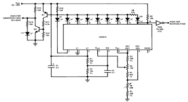
By utilizing several resistors, LEDs, and the LM3914 bar/dot display driver IC, it is possible to create a straightforward 5V voltmeter monitor circuit. This circuit offers TTL-compatible undervoltage and overvoltage warning signals. A complete circuit schematic is available below. The...

The primary component of this circuit is an operational amplifier (such as the 741 or 351), configured as an amplifier with a feedback circuit that consists of a diode bridge full-wave rectifier. An ammeter is connected to the rectifier...
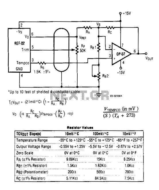
The DVM-to-temperature adapter is constructed around a single integrated circuit (IC), the National LM10. This micropower IC features a stable 0.2 V reference, a reference amplifier, and a general-purpose operational amplifier. The circuit is designed to operate within a...
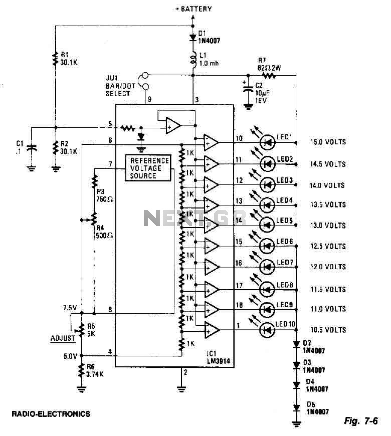
This screen utilizes ten LEDs to indicate a voltage range from 10.5 to 15 volts, with each LED corresponding to a 0.5-volt increment. The core component of the circuit is the LM3914 LED bar graph/display driver. A trimming potentiometer,...
In some cases, a differential input is needed for voltage measurement. By using a single operational amplifier, it is possible to construct an adapter that provides a floating voltage reference. To achieve a differential input for voltage measurement using an...
The circuit is a comparator that measures the voltage of a car battery in steps of 1 Volt. The voltage measurement is performed by comparing the battery voltage, applied to the inverting inputs of amplifiers, against reference voltages produced...