
RF-powered sidetone oscillator

The sidetone oscillator circuit typically incorporates a 555 timer IC configured in an astable mode, allowing it to generate a continuous square wave output. This output can be modulated by the RF signal received from a transmitter, which serves to turn the oscillator on and off. The keying mechanism is facilitated by applying a positive DC voltage to the reset pin of the 555 timer, effectively interrupting the oscillation when required.
In terms of design, the circuit consists of several key components: the 555 timer IC, resistors, capacitors, and a power supply. The resistors control the charge and discharge times of the timing capacitor, thus determining the frequency of the output waveform. The capacitor, in conjunction with the resistors, sets the oscillation frequency, which is crucial for the sidetone audio signal.
The RF signal is coupled to the reset terminal of the 555 timer, allowing the oscillator to be synchronized with the transmitter's operation. This ensures that the sidetone audio is generated only when the transmitter is active, providing an audible feedback to the operator. The battery power source ensures portability and ease of use in various field applications.
In summary, the sidetone oscillator serves as an essential component in communication systems, providing audio feedback during transmission while being efficient and compact due to the use of the 555 timer IC. Proper design and component selection are critical for achieving the desired performance characteristics in specific applications.A sidetone oscillator is a special audio astable multivibrator. Keying is accomplished oscillator that is turned on and off with the by applying a positive dc potential, developed transmitter. The oscillator is rf-driven and bat- from the rf signal, to the reset terminal of the tery operated It uses a 555 IC timer as an 555.
Related Circuits
This is an astable multivibrator (oscillator) circuit using a CMOS inverter. The circuit employs the CD4007 or MC14007 integrated circuit. The operating frequency range of this circuit is not specified. The astable multivibrator circuit utilizes CMOS technology to create a...
Understanding how quartz-crystal resonators operate can lead to designing crystal oscillators with improved stability and better noise performance. Quartz-crystal resonators function based on the piezoelectric effect, where mechanical stress applied to a quartz crystal generates an electrical charge. This property...
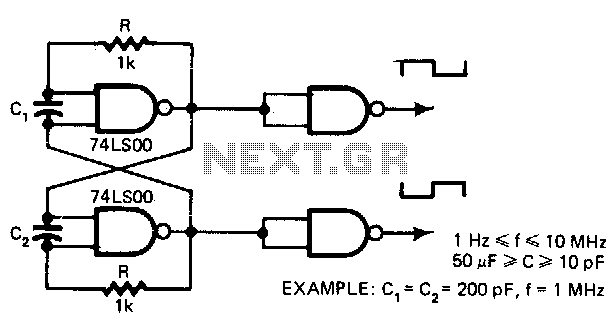
This low-cost oscillator is consistently self-starting and capable of operating from over 1 Hz to 10 MHz, requiring only five components. The period of oscillation can be calculated using the relationship: P = 5 x 10^3 C seconds when...
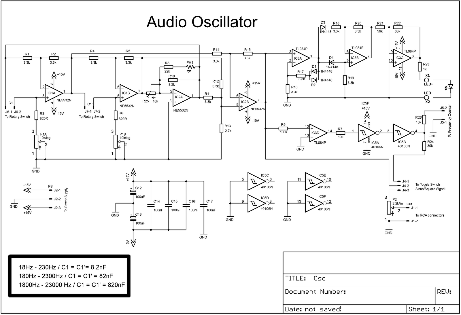
The project involves adding a DIY audio oscillator to a home workshop, which is essential for testing audio projects. While a basic oscillator is already available, it lacks a frequency counter. The design follows a schematic that provides a...
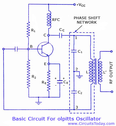
Colpitts oscillator circuit diagram and theory. Colpitts oscillator frequency equation. Colpitts oscillator using transistor. Colpitts oscillator using op-amp. The Colpitts oscillator is a type of electronic oscillator that generates sine waves and is widely used in various applications such as...
The generators of square pulses are used in a lot of applications, including the adjustment of conditions of entry in digital circuits and the control of acoustic frequency amplifiers. This circuit is a generator that produces, in combination with...