
selecting crystals stable oscillators
Quartz-crystal resonators function based on the piezoelectric effect, where mechanical stress applied to a quartz crystal generates an electrical charge. This property allows the crystal to oscillate at a precise frequency when an alternating voltage is applied. The frequency of oscillation is primarily determined by the physical dimensions and cut of the crystal, such as the thickness and angle of the cut, which can be tailored to achieve specific frequency characteristics.
In the design of crystal oscillators, the resonator is typically integrated into an oscillator circuit that includes active components such as transistors or operational amplifiers, along with passive components like capacitors and resistors. The oscillator circuit amplifies the oscillations produced by the crystal resonator, thus maintaining a stable output frequency.
Stability in crystal oscillators is enhanced by minimizing temperature variations and mechanical vibrations that can affect the resonator's frequency. Techniques such as temperature compensation and the use of high-quality factor (Q) crystals can significantly improve performance. Additionally, noise performance can be optimized through careful circuit design, including the use of low-noise components and power supply decoupling.
Overall, a thorough understanding of the operational principles of quartz-crystal resonators and their integration into oscillator circuits is essential for developing high-performance timing solutions in various applications, including communication systems, consumer electronics, and precision measurement instruments.Understanding how quartz-crystal resonators operate can lead to designing crystal oscillators with improved stability and better noise performance.. 🔗 External reference
Related Circuits
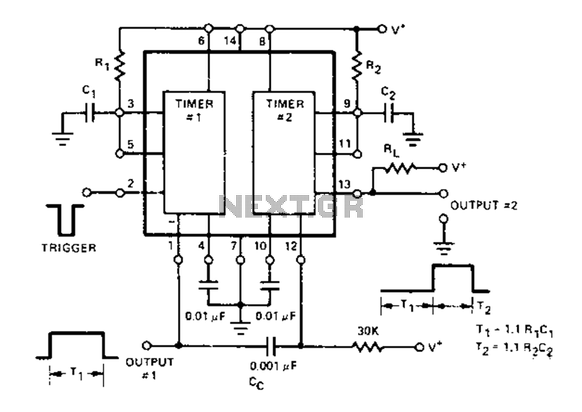
The Dual Timer Exar XR-2556 features a timing mechanism that can be triggered through capacitive coupling on a secondary timing pin. When a trigger input is engaged, the duration T1 can be set to 1.1R1C1, resulting in an increased...
In the 555 datasheet, there is a pulse width modulation circuit that resembles this one, with the only difference being that pin 5 is labeled as 'audio'. The 555 timer IC is a versatile device commonly used in various applications,...
Unlike conventional small-signal methods, employing large-signal, time-domain design techniques facilitates the creation of low-noise grounded-base oscillators suitable for VHF/UHF applications. The development of low-noise grounded-base oscillators for VHF/UHF applications presents unique challenges and opportunities. By utilizing large-signal, time-domain design techniques,...
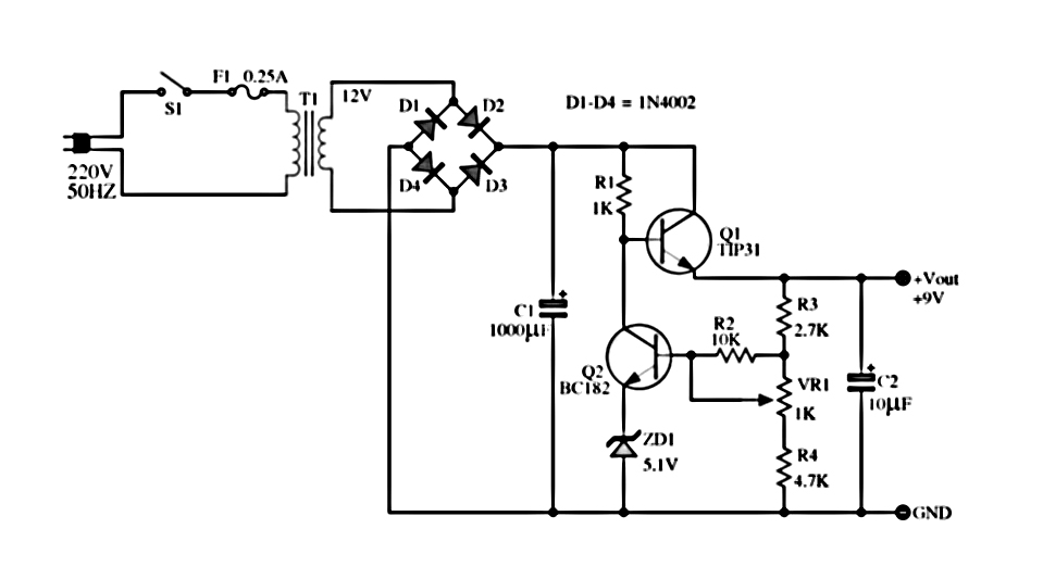
The power supply described utilizes a regulator composed of two NPN transistors. One transistor functions as the power regulator, while the other controls the output voltage. This power supply offers an adjustable output voltage range of 6-12 VDC. The...

The circuit utilizes a CMOS dual D flip-flop (CD4013) to toggle a relay or other load using a momentary push button. Multiple push buttons can be connected in parallel to control the relay from different locations. A high signal...

This circuit was first introduced by Signetics Corporation as the SE555/NE555 around 1971. Pin connections and functions are as follows: Pin 1 (Ground) is the most negative supply potential of the device, typically connected to circuit common when powered...
Warning: include(partials/cookie-banner.php): Failed to open stream: Permission denied in /var/www/html/nextgr/view-circuit.php on line 713
Warning: include(): Failed opening 'partials/cookie-banner.php' for inclusion (include_path='.:/usr/share/php') in /var/www/html/nextgr/view-circuit.php on line 713