
Rf-probe
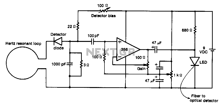
This RF probe is coupled with a fiber-optic connection to the test equipment. It utilizes inexpensive components to enhance probe performance at UHF frequencies. The receiving antenna in this probe feeds an envelope-detector diode. After amplification by the LF356 operational amplifier, the low-frequency output modulates the LED, which in turn feeds the optical fiber. The design allows for the use of a single battery for the operational amplifier, with voltage splitting achieved through a 1 kΩ potentiometer and miniature 47 µF tantalum capacitors to provide decoupling. The gain control is easily adjustable to optimize the dynamic range for a specific LED.
The RF probe is designed to operate effectively in the UHF frequency range, making it suitable for various applications in telecommunications and testing environments. The coupling with fiber-optic technology ensures minimal signal loss and high fidelity in signal transmission. The receiving antenna is crucial in capturing RF signals, which are then processed by an envelope detector. This diode converts the RF signal into a low-frequency envelope, which is then amplified by the LF356 operational amplifier, known for its low noise and high gain characteristics.
The output from the LF356 op-amp is used to modulate an LED, which acts as the light source for the fiber-optic transmission. The choice of LED is significant as it directly influences the efficiency of light coupling into the fiber. The gain control mechanism, implemented via a 1 kΩ potentiometer, allows for fine-tuning of the amplifier's output, ensuring that the dynamic range is optimized for the specific characteristics of the chosen LED. This adaptability is important for achieving the best performance under varying operational conditions.
Decoupling is achieved using miniature 47 µF tantalum capacitors, which help stabilize the power supply to the op-amp by filtering out noise. The use of a single battery simplifies the power management of the circuit, while the voltage splitting technique ensures that the operational amplifier receives the appropriate voltage levels for optimal performance.
Overall, this RF probe design is a cost-effective solution that leverages simple components to achieve reliable performance in UHF applications, making it an excellent choice for engineers and technicians working in RF testing and measurement.This rf probe is coupled with a fiber-optiCJ:able to the test equipment. It utilizes inexpensive components to improve probe performance at UHF frequencies. The receiving antenna in this probe feeds an envelope-detector diode. After amplification by the LF356 op amp, the low-frequency output modulates the LED, which in tum feeds the optical fiber. The design facilitates the use of a single battery for the op amp, with voltage splitting by means of the 1-K!l potentiometer, and miniature 47-I"F tantalum capacitors to provide decoupling. The gain control is easily adjusted to give the best dynamic range for a specific LED. 🔗 External reference
Related Circuits
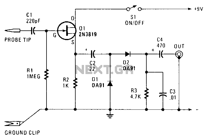
The transistor Q1 is configured as a source-follower buffer stage, providing slightly less than unity voltage gain. This configuration results in a high-impedance input of approximately 1 MΩ, shunted by about 10 pF, which minimizes loading on the equipment...