RF probes

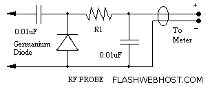
An RF probe is used to directly measure the level of RF voltage present at a particular point and is one of the most useful test instruments in the hands of the home brewer. It is normally used with a digital multimeter to indicate the voltage level as DC voltage, which is equivalent to the RMS value of the RF voltage being measured. However, the level of RF voltage being measured provides useful information only when the probe has been designed for use with a specific multimeter. The design of the RF probe is a function of the DC input resistance of the meter intended for use with it. If a new meter with a different input resistance is used with the probe, the reading will be inaccurate. Look at the figure below which shows the construction of the RF probe. The rectified DC voltage at the cathode of the diode is at about the peak level of the RF voltage at the tip. The value of the resistor R1 is so chosen that when this resistor is connected in parallel with the input resistance of the digital multimeter, the peak value is about 1.414 times the RMS voltage. R1 has to drop this excess voltage so the meter indication is accurate. If the input resistance of the meter is known, the value of R1 can be calculated as follows. Usually, digital multimeters have an input resistance of 11 megohms. In this example, the input resistance of the meter is taken as 10 megohms for ease of calculation.
10,000,000 X 1.414 = 14,140,000
R1 = 14,140,000 - 10,000,000 = 4,140,000 Ohms = 4.14 Meg Ohms
4.7 megohms is the value chosen in all circuits since digital multimeters have an input resistance of 11 megohms.
The RF probe circuit consists of a diode, typically a Schottky diode for its fast response time, which rectifies the RF signal. The probe tip is designed to connect to the RF source, allowing the RF voltage to be applied across the diode. The output of the diode is connected to the input of the digital multimeter (DMM) through resistor R1. The primary function of R1 is to ensure that the voltage read by the DMM corresponds accurately to the RMS value of the RF voltage.
In this configuration, the diode conducts during the positive half-cycles of the RF waveform, producing a rectified DC voltage at its cathode. The value of R1 is critical; it must be selected such that when it is combined with the input resistance of the DMM, it allows for a correct reading of the RF voltage. The calculation for R1 is based on the desired relationship between peak and RMS voltage, where the peak voltage is approximately 1.414 times the RMS voltage.
When designing an RF probe, it is essential to consider the input resistance of the multimeter that will be used. The standard input resistance for many digital multimeters is around 10 to 11 megohms. Therefore, the chosen resistor value (4.7 megohms) should be close to the calculated value of 4.14 megohms to maintain accuracy while ensuring compatibility with a range of multimeters.
In summary, the RF probe is a crucial tool for accurately measuring RF voltages, and its design must account for the specific characteristics of the multimeter used in conjunction with it. Proper selection of components, particularly the rectifying diode and the resistor R1, is vital for achieving precise measurements in various RF applications.An RF probe is used to directly measure the level of RF voltage present at a particular point and is one of the most useful test instrument in the hands of the home brewer. It is normally used with a digital multi meter to indicate the voltage level as dc voltage which is equivalent to the RMS value of the RF voltage being measured.
However, the level of RF voltage being measured provides useful information only when the probe has been designed for use with a specific multi meter. The design of the RF probe is a function of the DC input resistance of the meter we intend to use with it.
If a new meter with a different input resistance is used with the probe the reading will be inaccurate. Look at the figure below which shows the construction of the RF probe. The rectified DC voltage at the cathode of the diode is at about the peak level of the RF voltage at the tip. The value of the resistor R1 is so chosen that when this resistor is connected in parallel with the input resistance of the digital multi meter, the peak value is about 1.414 times the RMS voltage.
R1 has to drop this excess voltage so the meter indication is accurate. If we know the input resistance of the meter, we can calculate the value of R1 as follows. Usually, digital multi meters have an input resistance of 11 meg ohms. In this example we shall take the input resistance of the meter as 10 meg ohms which will make calculation easier to understand. 10,000,000 X 1.414 = 14,140,000 R1 = 14,140,000 - 10,000,000 = 4,140,000 Ohms = 4.14 Meg Ohms 4.7 meg ohms is the value chosen in all circuits since digital multimeters have input resistance of 11 meg ohms.
🔗 External reference

