
Making Differential Probes

To address the limitations of standard multimeters in measuring high current levels, a custom shunt resistor can be designed. A shunt resistor is a precise resistor placed in series with the load, allowing the current flowing through it to generate a voltage drop that can be measured by the multimeter.
To create a suitable shunt for measuring higher currents, the following specifications should be considered:
1. **Shunt Resistor Value**: The resistance value should be chosen based on the maximum current expected in the application. For instance, a shunt resistor of 0.01 ohms would allow for a maximum current of 10 amps to produce a 100 mV drop across it, which is within the measurement range of most multimeters.
2. **Power Rating**: The power rating of the shunt resistor must be sufficient to handle the heat generated by the current passing through it. The power can be calculated using the formula P = I²R, where P is the power in watts, I is the current in amperes, and R is the resistance in ohms. For example, a 0.01-ohm shunt carrying 10 amps would need to dissipate 1 watt of power.
3. **Connection Configuration**: The shunt should be connected in series with the load. Care must be taken to ensure that the multimeter is connected across the shunt resistor to measure the voltage drop accurately.
4. **Calibration**: It is important to calibrate the multimeter with the shunt resistor to ensure accurate readings. This can be done by measuring known currents and adjusting the multimeter readings accordingly.
5. **Safety Considerations**: When working with high voltages and currents, appropriate safety measures should be taken to prevent electrical shock or damage to the multimeter. This includes using insulated tools and ensuring that the circuit is powered off when making connections.
The implementation of a custom shunt resistor allows for an economical solution to measure high currents in DC powered projects, providing both accuracy and cost-effectiveness.Using a modern multimeter to measure current can sometimes be difficult. Many of these meters will only measure up to one amp. However, may 112-volt DC powered projects draw a lot more than that. If you have ever thought of purchasing a commercial shunt to solve the problem, your know just how expensive they can be. Commercial shunts, while very precise, frequently cost more than the projects they are measuring! 🔗 External reference
Related Circuits
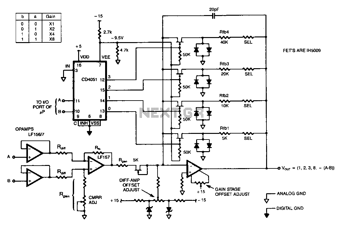
This programmable gain circuit utilizes a CD4051 CMOS Analog Multiplexer as a two to four line decoder, featuring appropriate FET drive for switching between feedback resistors to set the gain to one of four selectable values. The described programmable gain...
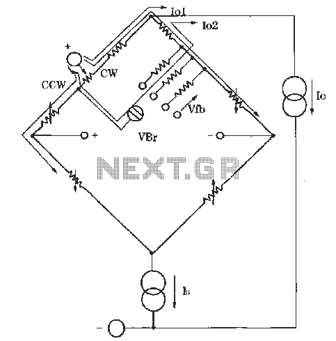
The circuit for zero and span adjustment consists of a feedback resistor network and a differential pressure sensing bridge measuring circuit. A constant current source, IO, represents the output current. The resistances of the four bridge arms are R1S,...
An RF probe is used to directly measure the level of RF voltage present at a particular point and is one of the most useful test instruments in the hands of the home brewer. It is normally used with...
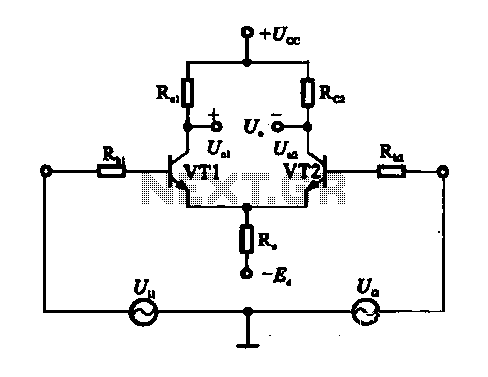
An emitter-coupled differential amplifier circuit is designed to suppress zero drift through circuit symmetry. The effectiveness of zero drift suppression improves with better symmetry; however, in practice, achieving complete symmetry is not feasible. Consequently, the basic differential amplifier circuit...
When designing a printed circuit board (PCB), a technique is employed to create a broad grounding pattern separate from the signal and power patterns. This approach is particularly useful for high-frequency circuits or when attempting to mitigate external noise...
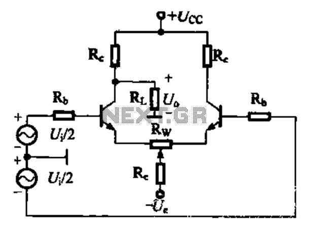
A comparison of four connection methods and features of a differential amplifier circuit is presented. The circuit demonstrates a magnification of a single tube with half the earnings, effectively countering common-mode negative feedback effects. The Common-Mode Rejection Ratio (CMRR)...