
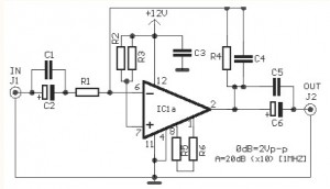
RF Recieving Amplifier for 40MHZ

The circuit employs a combination of resistors, capacitors, and transistors to achieve the desired amplification. The part list includes the following components:
- R1 = 75 ohm
- R2 = 10 K ohm
- R3-R7 = 5.6 K ohm
- R4-R5 = 4.7 K ohm
- R6 = 820 ohm
- R8 = 470 ohm
- R9 = 2.2 K ohm
- R10 = 68 ohm
- C1-C3 = 47 nF 100 V
- C2-C4 = 10 nF 100 V
- C5-C6 = 47 nF 100 V
- Q1-Q3 = AF125
- J1-J2 = Jack BNC
The RF amplifier utilizes AF125 transistors, which are well-suited for low-frequency applications. The resistors are selected to set the biasing conditions for the transistors, ensuring that they operate in the active region for optimal amplification. The capacitors are used for coupling and decoupling signals, as well as for filtering purposes to maintain signal integrity and reduce noise.
The input stage of the amplifier is designed to match the 75-ohm impedance of the coaxial cable, minimizing signal reflections and maximizing power transfer. The gain of 20 dB indicates that the output signal will be significantly stronger than the input, enhancing the receiver's sensitivity to weak signals. The circuit's power consumption of 7 mA is relatively low, making it suitable for battery-operated devices.
In summary, this RF amplifier circuit is a versatile solution for improving the sensitivity of receivers operating within the specified frequency range, utilizing common components to achieve effective signal amplification while maintaining compatibility with standard coaxial connections. The sensitivity of receiver it is possible to increase itself considerably, if is interfered, between this and his aerial, a amplifier RF. The amplifier of circuit, does not use in resonant circuits and for this is suitable, so much for mid waves, what for the low waves, up to the 40 MHZ.
The gain his it is the order 20db and it consumes 7mA, when it is supplied with 12 until 15V dc. His entry and the exit are adapted with coaxial cable, complex resistance 75ohm. Part List R1=75ohm R8=470ohm C5-6=47nF 100V R2=10Kohm R9=2.2Kohm Q1-2-3=AF125 R3-7=5.6Kohm R10=68ohm J1-2=Jack BNC R4-5 =4.7Kohm C1-3=47nF 100V R6=820ohm C2-4=10nF 100V 🔗 External reference
Related Circuits
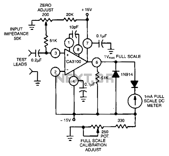
This circuit utilizes the CA3100 BiMOS operational amplifier to drive a 1-mA meter movement to its full scale with a 1-V RMS input. The circuit configuration incorporates the CA3100 BiMOS operational amplifier, which is known for its high input impedance...

Floating the grid above ground is detrimental for RF performance and arc protection. The connection of the control grid to ground is critical for stability. It is essential to keep the grid connection to ground as wide and short...
The video amplifier circuit utilizes the LM359 integrated circuit, which is a dual, high-speed, programmable current mode (Norton) amplifier. This circuit is suitable for general-purpose video amplification applications. The LM359 is designed to operate as a high-speed amplifier, making it...
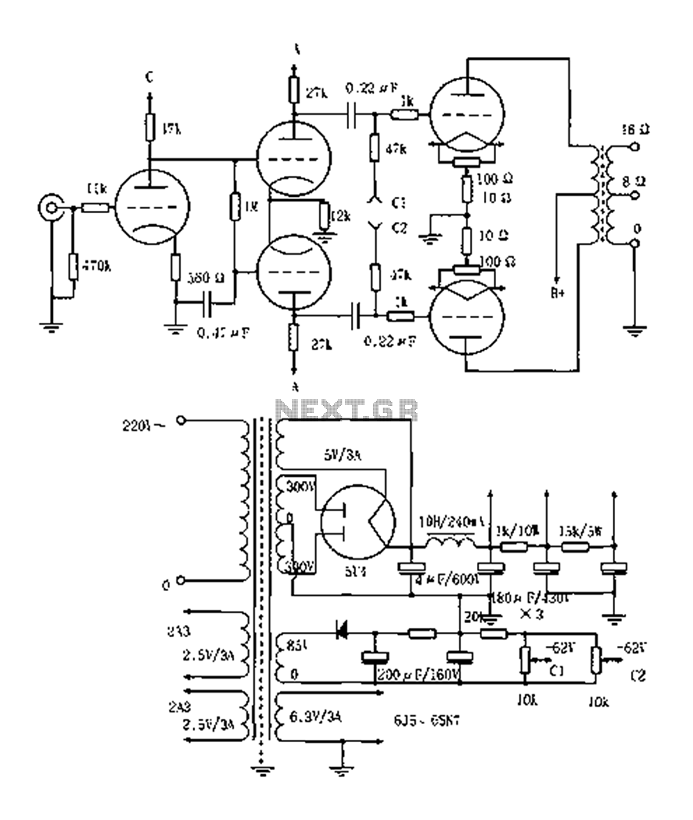
The Elliot 2A3PP line amplifier is a straightforward design, emphasizing the quality of the output transformer. It utilizes a 3KPP output transformer with a fixed bias of 62V, delivering an output power of 15W. The 2A3PP is well-suited for...
This circuit is primarily designed to provide a microphone input for standard home stereo amplifiers. Utilizing a battery supply effectively eliminates the risk of low-frequency hum interference from mains power, simplifying the connection to the amplifier by removing the...
Most devices used in amplifier output stages exhibit significant non-linearity, with transistors (both bipolar and FET) being particularly problematic. These components are almost always employed within a global feedback loop to mitigate their non-linear characteristics. Similarly, tetrode and pentode...