
portable microphone preamplifier circuit schematic

The circuit comprises several essential components that enable its functionality. The microphone input stage typically includes a preamplifier, which boosts the weak audio signal from the microphone to a more manageable level for further processing. This preamplifier can be implemented using operational amplifiers (op-amps) configured in a non-inverting configuration to maintain a high input impedance and low output impedance.
For stereo applications, two identical preamplifier circuits are required, each connected to its respective microphone input. Each preamplifier stage should include a gain control mechanism, which can be achieved through variable resistors or potentiometers. This allows for independent adjustment of the audio levels from each microphone, ensuring optimal balance and sound quality.
The output of the preamplifiers feeds into a coupling capacitor, which blocks any DC offset while allowing the AC audio signal to pass through to the amplifier input. The choice of capacitor value is crucial; it should be large enough to avoid significant attenuation of low-frequency signals while maintaining a compact design.
Additionally, a bypass capacitor may be included across the power supply lines to filter out any noise and ensure stable operation of the circuit. The entire assembly can be housed in a compact enclosure, with attention paid to grounding and shielding to minimize interference from external sources.
Overall, this circuit design provides a practical solution for integrating microphone inputs into home stereo systems, offering flexibility, ease of use, and enhanced audio performance while maintaining low power consumption for prolonged battery life.This circuit is mainly intended to provide common home stereo amplifiers with a microphone input. The battery supply is a good compromise: in this manner the input circuit is free from mains low frequency hum pick-up and connection to the amplifier is more simple, due to the absence of mains cable and power supply. Using a stereo microphone the circuit must be doubled. In this case, two separate level controls are better than a dual-ganged stereo potentiometer. Low current drawing (about 2mA) ensures a long battery life.. 🔗 External reference
Related Circuits
An automatic power protection circuit is presented. This protection includes a step-down rectifier circuit, an overvoltage and undervoltage detection circuit, and a delay switch control circuit. The step-down circuit is responsible for the entire rectifier circuit's DC voltage. The automatic...
The voice circuits discussed in this section operate such that during daylight or in bright conditions, the voice-activated switch remains off, preventing the lamp from lighting. Conversely, in low-light conditions or at night, the sound control switch is activated....
Boss MT2 Metal Zone Distortion Pedal Schematic. The MT-2 Metal pedal is one of the most popular guitar pedals, providing over-the-top, insane distortion tones with huge mids and lows and an ultra-saturated sound. The Boss MT-2 Metal Zone Distortion Pedal...
An idea proposed is to utilize a phase shift oscillator followed by an inverter to convert a sine wave into a square wave; however, this may be considered a rudimentary solution. There is also interest in schematics for a...
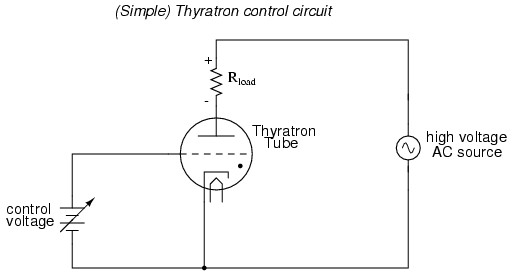
An often neglected area of study in modern electronics is that of tubes, more precisely known as vacuum tubes or electron tubes. Almost completely overshadowed by semiconductor, or "solid-state" components in most modern applications, tube technology once dominated electronic...
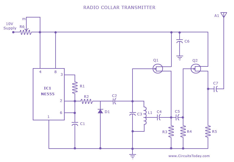
This is a radio transmitter circuit diagram designed for integration into radio collars using the NE 555 integrated circuit. The circuit transmits a pulse in the FM band, specifically between 88 MHz and 105 MHz. The radio transmitter circuit utilizes...