
0,4 Watt FM transmitter

Capacitors: C1, C2, C12 - 100 pF (ceramic) C3, C5 - 0.22 uF (electrolytic) C4 - 1.8 nF (plastic) C13, C16, C17, C19 - 1 nF (ceramic) C8, C9 - 10 pF (ceramic) C10 - 47 pF (ceramic) C11 - 8.2 pF (ceramic) C14 - 60 pF trimmer C15 - 35 pF trimmer C18, C7 - 100 nF (ceramic) C20 - 470 uF (electrolytic, 16 V)
Coils: (All coils are free-standing air-core types, wound of 0.7 mm Cu wire, 6 mm internal diameter.) L1 - 4.5 coils L2 - 9.5 coils L3 - 4.5 coils
Resistors: R1, R2 - 10 k pot. R3 - 33 k R4, R7, R12 - 10 k R5, R11 - 470 R6 - 27 k R8 - 22 k R9 - 270 R10 - 100
Misc.: D1 - BB409 (BB109G, BBY31) varicap T1 - BC547C (BC548C, BC547B) T2 - BFR91A (BFR96) T3 - BFR96
Antenna Power supply 3.5 mm jack CD player, computer 6 V / 0.1 A bulb
The circuit described operates as a wideband FM transmitter, utilizing a power supply of 12-14 V with a current rating of 100 mA. The transmitter is designed to deliver an RF power output of 400 mW, suitable for broadcasting in the frequency range of 87.5 to 108 MHz, which encompasses the FM radio band. The impedance level of this circuit is adaptable, allowing it to operate effectively within the range of 50 to 75 ohms.
The circuit incorporates a 6 V / 0.1 A bulb connected to the output, serving as a visual indicator of power output. The tuning process involves adjusting the variable resistor R1 to find the optimal frequency. The coil L1 can be fine-tuned by adjusting the number of turns, which influences the inductance and, consequently, the operating frequency. Capacitors C14 and C15 are trimmer capacitors used to maximize the output power, indicated by the brightness of the bulb.
The antenna connection is crucial for effective transmission, and it is recommended to use a dipole antenna placed outdoors at a height for optimal coverage. The circuit is capable of achieving a coverage range of approximately 500 meters under good conditions, with the potential for maximum coverage extending up to 4 kilometers.
The components list includes various capacitors, coils, resistors, and transistors, all chosen for their specific roles in the circuit. The capacitors range from ceramic to electrolytic types, with values selected for tuning and filtering purposes. The air-core coils are constructed from 0.7 mm copper wire, ensuring minimal losses and efficient RF performance.
Transistors T1, T2, and T3 serve as the active amplification elements in the circuit, with T1 being a BC547C, suitable for low-power applications, and T2 and T3 being BFR91A and BFR96, respectively, optimized for RF amplification. The circuit also includes a varicap diode (D1) for frequency modulation, allowing for dynamic tuning based on the input audio signal.
Overall, this circuit represents a compact and efficient design for a wideband FM transmitter, with careful consideration of component selection and circuit topology to achieve the desired performance characteristics.Power supply: 12-14 V stab., 100 mA. RF power: 400 mW. Impedance: 50-75 ohm. Frequency range: 87,5-108 MHz. Modulation: wideband FM. Connect the 6 V / 0,1 A bulb to the output and use R1 to tune the right frequency. Maybe you might stretch coils of the L1. Then use C14 and C15 to adjust the highest power (the highest light of the bulb). Then you can connect antenna and audio signal. Adjust R2 until the audio sounds as loud as the other stations. With good antenna (dipole placed outdoor and high) the transmitter has very good coverage range about 500 meters, the maximal coverage range is up to 4 km. Parts list Capacitors: C1, C2, C12 - 100 pF (ceramic) C3, C5 - 0,22 uF (electrolytic) C4 - 1,8 nF (plastic) C13, C16, C17, C19 - 1 nF (ceramic) C8, C9 - 10 pF (ceramic) C10 - 47 pF (ceramic) C11 - 8,2 pF (ceramic) C14 - 60 pF trimmer C15 - 35 pF trimmer C18, C7 - 100 nF (ceramic) C20 - 470 uF (electrolytic, 16 V) Coils: (All coils are free-standing air-core types, wound of 0,7 mm Cu wire, 6 mm internal diameter.) L1 - 4,5 coils L2 - 9,5 coils L3 - 4,5 coils Resistors: R1, R2 - 10 k pot. R3 - 33 k R4, R7, R12 - 10 k R5, R11 - 470 R6 - 27 k R8 - 22 k R9 - 270 R10 - 100 Misc.: D1 - BB409 (BB109G, BBY31) varicap T1 - BC547C (BC548C, BC547B) T2 - BFR91A (BFR96) T3 - BFR96 Antenna Power supply 3,5 mm jack CD player, computer 6 V / 0,1 A bulb
🔗 External reference
Related Circuits
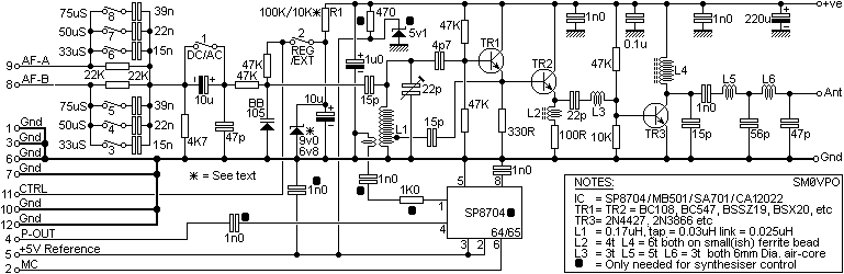
TR1 (BC547) is an inverted Hartley oscillator which based upon an inductor fabricated on the PCB. This makes it megga-stable, and setable anywhere in the VHF FM band (76MHz to 119MHz) and the BB105 varicap makes it voltage tuneable...
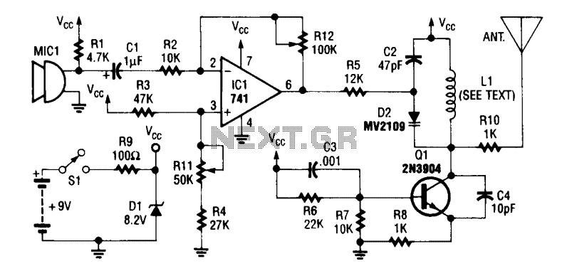
An operational amplifier integrated circuit (741) amplifies the audio signal from microphone MIC1, with resistor R12 adjusting its gain. The amplified audio is directed to the oscillator circuit, which includes transistor Q1 and associated components. D2 is a varactor...
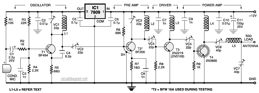
A four-stage FM transmitter circuit diagram utilizes four radio frequency stages: a VHF oscillator designed around the BF494 transistor (T1), a preamplifier based on the BF200 transistor (T2), a driver built with the 2N2219 transistor (T3), and a power...
This project, based on an article published in the February 2008 edition of Radcom (the magazine of the Radio Society of Great Britain), describes a meter with a 50-ohm input impedance designed for measuring very small RF powers. Many...
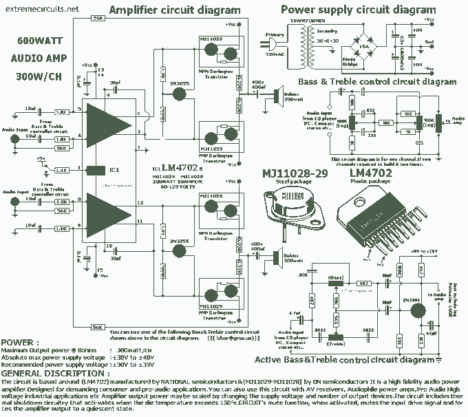
The circuit is based around LM4702 manufactured by NATIONAL semiconductors MJ11029-MJ11028 by ON semiconductors. It is a high fidelity audio power amplifier designed for demanding consumer and pro-audio applications. You can also use this circuit with AV receivers, audiophile...
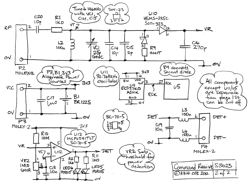
The Command Transmitter-Receiver (A3023) is designed to test the command receiver proposed for the Implantable Sensor with Lamp (ISL) in the conceptual design phase. The A3023 consists of two primary components: the Command Transmitter section, which features a 146-MHz...