
FM transmitter microphone

The circuit utilizes the operational amplifier (op-amp) 741, which is a versatile device commonly used in audio applications due to its high gain and low noise characteristics. The microphone (MIC1) captures audio signals, which are then sent to the op-amp for amplification. The gain of the op-amp is set by resistor R12, allowing for customization based on the required output level.
The amplified audio signal is then fed into an oscillator circuit, which is primarily composed of transistor Q1. This transistor is responsible for generating a carrier frequency that can be modulated. The modulation process is accomplished using D2, the varactor diode, which changes its capacitance based on the input audio signal. This change in capacitance alters the frequency of the oscillator, resulting in frequency modulation (FM) of the output signal.
Inductor L1, constructed with three turns of #18 gauge wire, plays a crucial role in the oscillator circuit by providing the necessary inductance to work in conjunction with the varactor diode. The choice of wire gauge and the number of turns are critical for achieving the desired inductance value, which impacts the overall performance of the oscillator.
The antenna, designed as a 12-inch whip, is used to transmit the modulated signal. The length of the antenna is selected to optimize transmission efficiency at the operating frequency, ensuring that the signal can be effectively radiated into the surrounding environment. Overall, this circuit design is suitable for applications requiring audio transmission via frequency modulation, providing a compact and efficient solution for wireless audio communication.An op-amp IC (741) amplifies the audio signal from MIC1, and R12 controls its gain. Audio is fed to the oscillator circuit Q1 and related components. D2 is a varactor diode. Audio fed to D2 causes FM of the oscillator signal. L1 is 3 turns of #18 wire. The antenna is a 12" whip.
Related Circuits
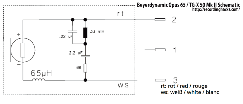
The Mk II was a second-generation version of the TG X 50. Both were dynamic microphones intended for bass instruments and kick drums. The primary difference between the two versions was the introduction of a passive EQ filter in...

This FM transmitter project is a simple yet effective circuit capable of transmitting signals over a distance of up to 1 kilometer in open air conditions. The circuit employs an RF transistor in the output stage, along with two...
The circuit is basically a radio frequency (RF) oscillator that operates around 100 MHz. Audio picked up and amplified by the electret microphone is fed into the audio amplifier stage built around the first transistor. Output from the collector...
These two tank circuits appear to broaden the operating spectrum. The accompanying information sheet indicates that when both circuit stages oscillate at the same frequency, the power output reaches its maximum. This suggests that if the tunable tank circuit...

The preamplifier is designed for use with dynamic (moving coil, MC) microphones that have an impedance of up to 200 ohms and feature balanced terminals. It is relatively straightforward. The preamplifier circuit serves as a crucial interface between the microphone...

This circuit is designed to generate audio musical notes that can be heard from a distance of up to 10 meters. The circuit consists of two main components: an infrared (IR) music transmitter and an IR music receiver. The...