
Ne602 Direct Conversion Receiver Circuit
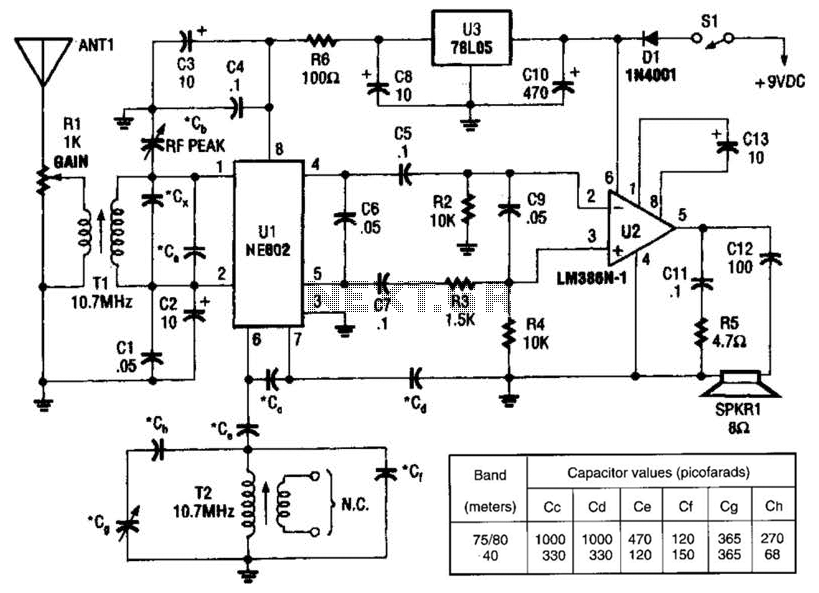
The NEC602 is a versatile integrated circuit that operates effectively in low-power applications. Its primary function as a mixer allows it to combine radio frequency (RF) signals with a local oscillator signal, resulting in a zero IF output. This configuration simplifies the design of the receiver by eliminating the need for additional filtering stages typically required in conventional superheterodyne receivers.
The audio amplifier (U2) connected to the output of the NEC602 is responsible for amplifying the demodulated audio signals, ensuring they are at a suitable level for further processing or output to speakers or headphones. This stage is crucial for providing clear audio reproduction of the received SSB and CW signals.
The use of 10.7-MHz IF coils (T1 and T2) is standard practice in many radio applications, particularly in AM/FM receivers. These coils are optimized for the 10.7-MHz frequency, which is the typical IF frequency for FM broadcast receivers. In the context of this circuit, they facilitate the filtering and amplification of the signals before they reach the mixer stage, enhancing overall performance and selectivity.
This receiver design is particularly advantageous for amateur radio enthusiasts and applications where SSB and CW communications are prevalent, as it provides a compact and efficient solution for receiving and processing these types of signals. The combination of the NEC602 mixer and the audio amplifier allows for a streamlined approach to radio signal processing, making it suitable for a variety of radio communication projects. An NEC602 is used as a mixer with a zero IF frequency output, U2 acts as an audio amplifier. This receiver is primarily for SSB and CW signals. Tl and T2 are 10.7-MHz IF coils used in AM/FM transistorized radios, etc. or in any similar indicator. 🔗 External reference
Related Circuits
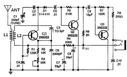
All coils are designed using an inch diameter PVC pipe with 20-gauge insulated hookup wire. L1 requires 6 turns, while L2 requires 14 turns. Additional turns can be added or subtracted from L1 or L2 (or C2 can be...
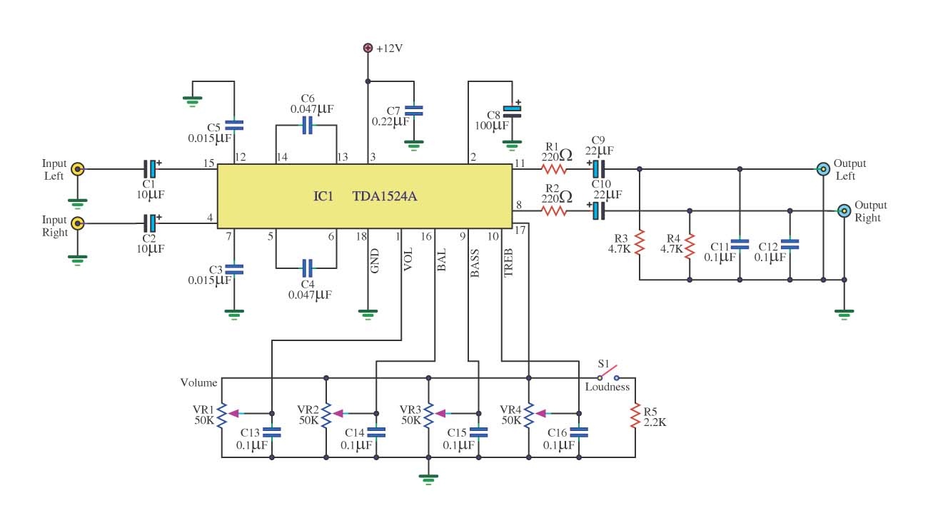
This is a simple tone control circuit using the TDA1524A, which is a key component in this IC chip diagram from Philips. The circuit allows for tone control adjustments such as bass, treble, and balance, enabling users to fine-tune...
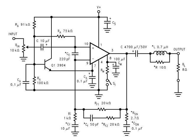
The LM2876 audio power amplifier circuit can be designed as a simple, high-efficiency power audio amplifier capable of delivering 40W of continuous average power to an 8-ohm load with a total harmonic distortion plus noise (THD+N) of 0.1% from...
The integrated circuit input side contains an oscillating circuit, where the oscillation frequency is determined by the external components L1, C1, and the sensor's equivalent capacitance. The equivalent capacitance increases as the sensor is immersed in liquid. The oscillating...
This circuit is a small +5V power supply, which is useful when experimenting with digital electronics. Small inexpensive wall transformers with variable output voltage are available from any electronics shop and supermarket. Those transformers are easily available, but usually...

This is a design for a scoring game circuit suitable for any occasion where dice are used. The circuit utilizes a NE555 timer, a 74LS192 counter, a 74LS247 decoder, and a seven-segment LED display. The timer IC1 generates a...