
AM/cw 20-meter band transmitter

The circuit described is a low-power AM transmitter designed for simple audio broadcasting applications. The core component of this circuit is a crystal oscillator integrated circuit, which provides a stable frequency output. This frequency is critical for AM transmission, ensuring that the signal can be effectively received by standard AM radio receivers.
The circuit can accommodate two types of microphones: an electret microphone and a dynamic microphone. The electret microphone is preferred due to its higher output voltage, which typically exceeds the required 100mV. In cases where a dynamic microphone is utilized, the circuit may require an additional low-frequency (LF) preamplifier stage, which can be implemented using a single transistor. This stage amplifies the microphone's output to a sufficient level, allowing for effective modulation of the AM signal.
The collector modulated AM oscillator is responsible for modulating the audio signal onto the carrier wave generated by the crystal oscillator. This modulation process occurs when the audio signal varies the collector current of the transistor, thereby modifying the amplitude of the carrier wave. The output of this modulation can be transmitted through the air and received by any standard AM radio receiver, demonstrating the fundamental principles of amplitude modulation.
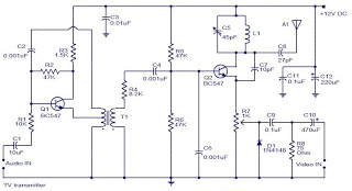
It is important to note that while this circuit provides a basic understanding of AM transmission, more sophisticated circuits used in professional radio stations incorporate additional components to enhance signal quality, range, and stability. Nonetheless, this simple circuit serves as an excellent introduction to the concepts of audio broadcasting and radio frequency transmission. Proper attention should be paid to the power supply and antenna design to maximize the transmission range and effectiveness of the circuit.In this project, you will make a simple low-power broadcast-type circuit, using a crystal oscillator integrated circuit and an a collector modulated AM oscillator. You can connect the circuit to the an electrec microphone (pointed out in gray on the diagram) or amplified dynamic microphone (no amplified microphone has a to low output voltage to work.
Approx. 100mv is needed). You could also add a LF preamp stage of one transistor to allow connecting a dynamic microphone directly. You`ll see that you can receive the signal through the air with almost any AM radio receiver. Although the circuits used in radio stations for AM receiving are far more complicated, this nevertheless gives a basic idea of the concept behind a princip 🔗 External reference
Related Circuits
The camera is oriented to look out the side of the rocket during launch and downward during descent on the parachute. An optional external mirror can be added to enable the camera to look down during lift-off. The transmitter...
This project is about an IR-detector (Infra Red) combined with a 100mW 50MHz transmitter. The detector is sensitive to changes in IR-spectrum and is commonly used in burglar alarms. When the detector senses a person/animal/ghost/angry clown, it will transmit...

This FM transmitter circuit is very simple and has acceptable transmission. The signal transmitted from this FM transmitter circuit can be received at almost 300 meters in open air. The circuit requires a 3-volt operating voltage and can be...
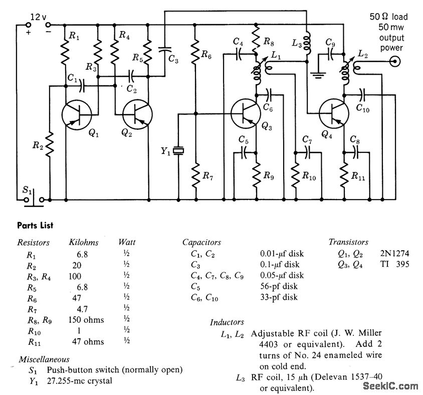
A free-running multivibrator activates power amplifier Q4 for audio applications. The operational range is approximately 1 mile, and capacitor C6 is used to tune the collector of the oscillator to the crystal frequency. - Texas Instruments Inc., "Transistor Circuit...
The transceiver is composed of three single-sided printed boards 100x70 mm; these may be stacked to reduce the overall size of the metal cabinet. It is suggested to employ small size components (1/4 W resistors, 2.5 mm capacitors) which...
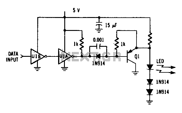
The driver circuit utilizes an MC74LS04 and a discrete transistor. The circuit is capable of driving the LED (MFOE12QO) at data rates of up to 1 Mbps. The driver circuit employs the MC74LS04, which is a hex inverter, to provide...