
Transceiver for 20 m band


The transceiver design incorporates a compact and modular approach, utilizing three single-sided printed circuit boards (PCBs) measuring 100x70 mm. This configuration not only facilitates the stacking of the boards to minimize the physical footprint but also allows for efficient thermal management and signal integrity. The choice of small components, such as 1/4 W resistors and 2.5 mm capacitors, is critical to ensure that all components fit seamlessly onto the PCB without compromising performance.
The front panel layout is user-centric, featuring essential controls such as the tuning potentiometer, gain and volume controls, as well as input/output jacks for key and earphone connections. The rear panel is designated for the power supply and antenna connections, promoting organized cabling and ease of access.
At the heart of the transceiver is a Colpitts FET oscillator, which provides the necessary frequency generation for both receive (RX) and transmit (TX) operations. The buffer transistor, typically a 2N2222, is employed to drive the RF circuits effectively, ensuring that signal integrity is maintained across the frequency range. The transceiver exhibits optimal performance in the frequency range of 7 to 8 MHz, beyond which stability may be compromised. To adapt the transceiver for higher frequency bands, such as 14 MHz, a conversion VFO version is recommended. This adaptation is achieved by modifying the connection of capacitor C5, allowing for flexibility in application.
The circuit design emphasizes the need for NPO-type capacitors where specified, due to their temperature stability and low loss characteristics, which are essential for RF applications. The careful winding of the tuning coil is crucial; for the 14 MHz band, L1 is constructed using 50 turns of 0.40 mm enameled wire around a 13 mm plexiglass core. This design choice contributes to the desired frequency span of approximately 70 kHz, covering the range from 2.433 to 2.510 MHz, with an output level of 4V pp.
The integration of varactor diodes in the BB204 package, connected in parallel, is a key aspect of the tuning mechanism, allowing for fine adjustments in frequency. The coils L2 and L3, specifically designed for the 14 MHz band, are fabricated using 12 turns of 0.50 mm enameled wire on a T44-2 toroidal core, with a three-turn link on L2 to enhance coupling and tuning precision. Overall, this transceiver design exemplifies a balance between compactness, performance, and user accessibility, making it suitable for various amateur radio applications.The transceiver is composed by three single sided printed boards 100x70 mm, theese may be stacked so as to reduce the overall size of the metal cabinet. I suggest to employ small size components (1/4 W resistors, 2,5 mm capacitors, ) wich should fit better on the PCB boards.
On the front panel you may place the tuning pot with its reductor gear, the gain and volume controls, the Key and earphone jacks. The power and antenna connectors may be housed on the back panel. The basic version makes use of a Colpitts fet oscillator and a buffer (2N2222) driving the RX and TX circuits.
It works very well up to 7 or 8 Mhz, above this limit the stability may be impaired, therefore if you want to adapt this transceiver for a high-bands use (this is the case of 14 MHz band), it will be better to choose the conversion VFO version, wich makes use of the whole PCB board. You may shift from a version to the other simply by changing the connection of the C5 capacitor. The basic circuit version doesn't use the conversion components (located in the lower part of the schematic) Where specified, the capacitors must be NPO type.
The tuning coil must be wound very carefully. A multi-turn pot may be employed for the tune control, but this will make the building of a frequency reading scale more difficult. The L1 coil for the 14 Mhz band is made by 50 turns of enameled 0.40 mm wire wrapped on a 13 mm plexiglass core.
The specified component values allow a frequency span of about 70 KHz (from 2,433 to 2,510 Mhz) and the output level will be 4V pp. The two varactor diodes contained in the BB204 must be parallel connected. The L2 and L3 coils for the 14 Mhz band are obtained wrapping 12 turns of 0.50 mm enameled wire on a toroidal core T44-2.
The link on L2 is made by 3 turns of plastic insulated wire. 🔗 External reference
Related Circuits
A bandpass filter allows a specific range of frequencies to pass while rejecting frequencies that fall outside the upper and lower limits of the passband. The frequencies that are permitted to pass are referred to as the passband, which...
While developing an infrared (IR) extender circuit, a method was needed to measure the relative intensities of different infrared light sources. This circuit utilizes an SFH2030 photodiode as the infrared sensor. A CA3140 MOSFET operational amplifier is employed in...
The regenerative detector uses a field effect transistor (FET). Like with the better valve designs, feedback is controlled by a variable capacitor. A ferrite rod was used to allow reception of local stations without an external antenna. This FET...
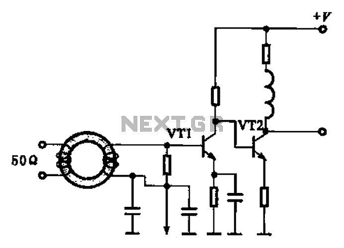
A broadband high-frequency amplifying circuit is primarily composed of a high-frequency matching transformer and an amplifying transistor. This circuit is designed to handle large high-frequency signals. The input of the amplifier circuit utilizes a matching transformer to ensure that...
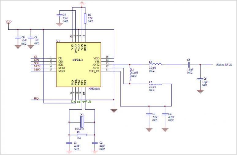
The NRF24L01 is a single-chip radio transceiver designed for operation within the 2.4 to 2.5 GHz ISM band. The NRF24L01 transceiver is a highly integrated solution that facilitates wireless communication in the 2.4 GHz ISM band, making it suitable for...
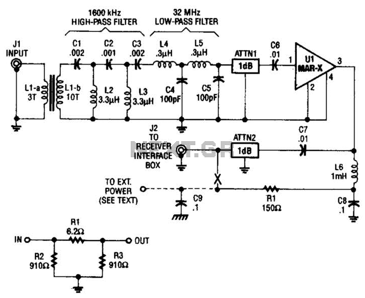
The HF/SW receiver preamplifier consists of a broadband toroidal transformer (LI-a and Ll-b), an LC network featuring a 1600-kHz high-pass filter and a 32-MHz low-pass filter, inductors L2 and L3 (26 turns of #26 enameled wire wound on an...