
RIIA Phone attenuator / Filter

The circuit described functions as a line input to phono input converter, allowing modern audio equipment to interface with older amplifiers that primarily feature phono inputs. The design incorporates an attenuator and a filter to ensure compatibility and signal integrity.
The attenuator reduces the amplitude of the line-level signal, which typically ranges from 0.5V to 2V, down to the lower voltage levels expected by a phono input, which is usually around 0.1V or less. This is achieved by the resistor values selected for R1, R2, and R3. R1, with a value of 1 MΩ, serves as the primary resistor in the voltage divider configuration, while R2, at 82 kΩ, provides the necessary attenuation to ensure that the output does not exceed the acceptable input range for the phono stage of the amplifier.
The filter section of the circuit is designed to implement the RIAA equalization curve, which is a standard used in vinyl playback to ensure that the frequency response of the audio signal is consistent with the recording characteristics. Capacitors C1 through C4, each valued at 1 nF, are employed to create a high-pass filter that compensates for the frequency response of the phono cartridge. The arrangement of these capacitors in conjunction with the resistors forms a low-pass filter that effectively reverses the RIAA correction applied during the vinyl mastering process.
The input signal is fed into the circuit at the "in" terminal, where it undergoes attenuation and filtering before being output at the "out" terminal, which is then connected to the phono input of the amplifier. This allows for seamless integration of modern line-level sources, such as CD players or digital audio players, into older audio systems without compromising audio quality or performance.
Overall, this circuit design is crucial for bridging the gap between contemporary audio equipment and legacy systems, ensuring that users can enjoy high-fidelity sound reproduction from various sources.In older amps is usually a phono input. Today, this used less and less, and it would be useful if the input and line input can be used. This circuit goes. The circuit is actually an attenuator and a filter. The signal is attenuated to the level of a phono pickup, and filtered so that the RIAA correction amplifier is reversed. On "in" comes the line signal, and "out" is connected to the phono input of the amplifier. Parts List R1 = 1 M ½ 1% R2 = 82 kOhm 1% R3 = 1 kOhm 1% C1-C4 = 1 nF 1% Styroflex 🔗 External reference
Related Circuits
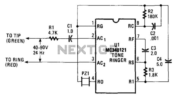
The AC ringing voltage, typically ranging from 40 to 90 V at 26 Hz, is rectified by U1, the tone-ringer integrated circuit (IC), which is utilized to drive the internal tone-generator circuitry. This tone-generator IC comprises a relaxation oscillator...
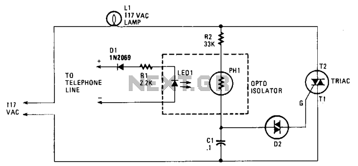
When the phone rings, the triac is activated into conduction by a signal applied to its gate (G) through a bilateral switch (diac), D2. The triac functions as a switch, conducting only when a signal is present at the...
The traditional transistor power supply features a large filter capacitor on the rectifier output, followed by an electronic regulator that eliminates all voltage fluctuations, including ripple. During the era of vacuum tubes, only high-end test equipment from manufacturers like...
This circuit generates a ringing sound similar to that produced by modern telephones. It comprises three nearly identical oscillators connected in a series configuration, each generating a square wave signal. The frequency of each oscillator is determined by the...
This preamplifier uses a type of IC 741 and can boost a microphone signal to line level. The microphone signal is connected to the input port. Any power for the microphone jack of the food are met. Here half...
Currently, there is a growing trend to utilize telephone lines for long-range control and alarm systems within transmission mediums, which is accompanied by extensive research. Such systems typically consist of alarm devices and police notification arrangements, including a central...