
Ring counter with variable timing

The circuit utilizes unijunction transistors (UJTs) to generate shift pulses, which are essential for timing and control in various electronic applications. The timing intervals between these pulses are governed by two critical components: the capacitor (CT) and the resistor (RT). The capacitor charges and discharges, which influences the timing of the pulse generation.
In this configuration, the resistor RT can be varied for each stage of the counter, allowing for flexible control over the pulse width and frequency. This feature enables the design to accommodate different operational requirements and adjust the timing characteristics of each stage independently. The selection of RT is crucial as it directly affects the rise and fall times of the pulses, thereby impacting the overall performance of the counter system.
When designing the circuit, attention should be given to the values of CT and RT, as they determine the duration of the pulses and the intervals between them. The UJT's intrinsic properties, such as its triggering voltage and the characteristics of the associated components, will also play a significant role in the stability and reliability of the pulse generation.
In practical applications, this circuit can be employed in timing circuits, pulse generators, and as part of more complex digital systems where precise timing is essential. The ability to select different resistors for each stage adds versatility, making it suitable for a wide range of uses in electronic devices.Shift pulses are generated by the unijunction transistors. The intervals between pulses are controlled by CT and RT. A different RT can be selected for each stage of the counter as shown.
Related Circuits
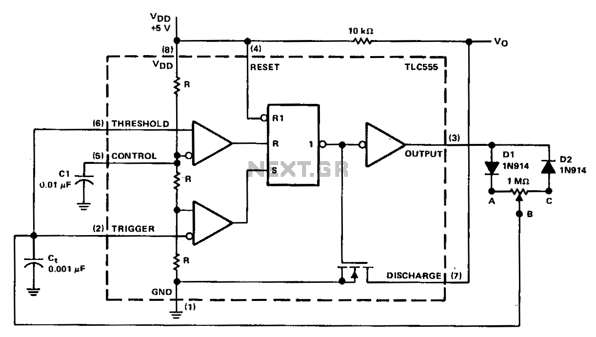
In a basic astable timer configuration, timing periods 11 and 12 are not independently controlled. This lack of control complicates the maintenance of a constant period, T, when either 11 or 12 is varied. In this circuit, the charge...
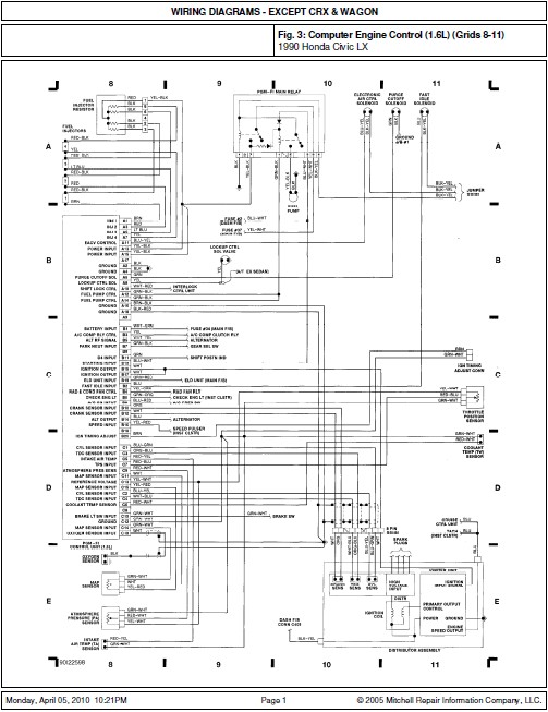
This document contains the wiring diagram for the 1990 Honda Civic LX. It includes diagrams for the Computer Engine Control (1.6L) located in grids 8-11, the Steering Column and A/C Heat systems in grids 20-23, as well as the...
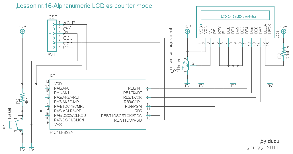
The communication technique with the LCD is similar to the previous lesson. In this experiment, a counter that counts from 0000 to 9999 has been added. The counter increments with a 1-second delay. The communication with the LCD will...
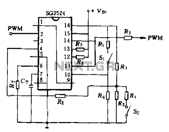
The SG3524 is utilized solely as a pulse width modulator. The error amplifier is configured in a follower arrangement. As illustrated in Figure 10-7, the ACR output connects to PWM output pin 2, which serves as the control signal....
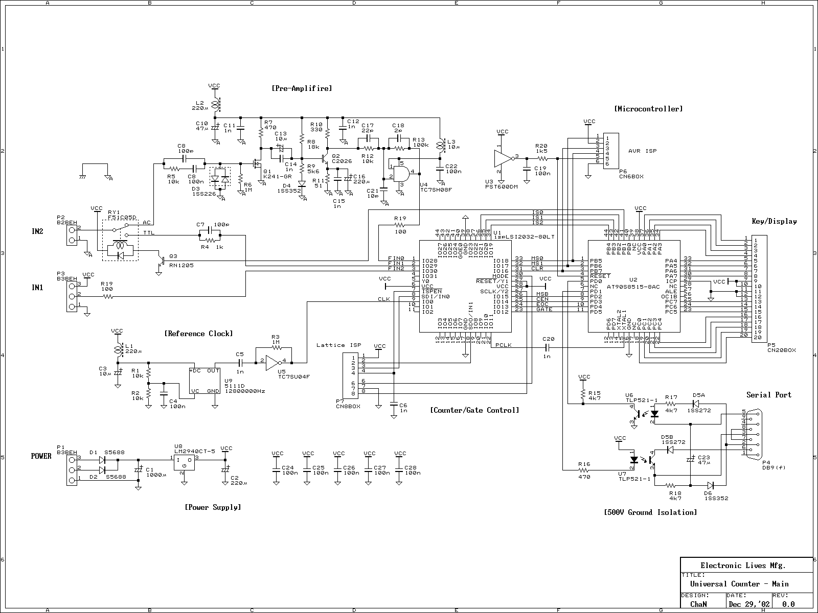
The frequency counter is the most popular instrument in home-made instruments. The reason it is built widely is that it can be built easily because it is a digital circuit, it is a generic measurement, and many construction kits...
The material is presented as a teaching tool aimed at enhancing understanding and interest in the design of counters. According to R. S. S. Obermann, the design of counters serves as an excellent proving ground for individuals who have...