
Robot eyes circuit

The robot eyes circuit is designed to create a visual effect that simulates the blinking or movement of human eyes using two lamps. This circuit typically employs a dual-lamp configuration, where each lamp represents an "eye." The operation is characterized by an unsteady blinking pattern, which can be achieved through the use of a timer or oscillator circuit.
To implement this circuit, a 555 timer IC can be utilized in astable mode to generate a square wave output. The frequency of the blinking can be adjusted by changing the resistor and capacitor values connected to the timer. The output from the timer can then be used to drive two LEDs or small incandescent bulbs, which will illuminate alternately to mimic the natural blinking of eyes.
The circuit diagram will include the 555 timer, resistors, capacitors, and the dual lamps. Proper power supply connections must be made to ensure the circuit operates effectively. Additionally, the circuit can be enhanced with a potentiometer to allow for adjustable blinking speed, providing further customization of the visual effect.
Overall, this robot eyes circuit serves as an engaging and educational project, demonstrating basic electronic principles while producing a visually interesting output.Robot eyes circuit of Service A simple circuit to simulate a man appointed to It is a dual-lamp working in a manner UNSTEADY Circuit diagram. 🔗 External reference
Related Circuits

This is a hobby circuit designed as a water or liquid sensor. Its primary function is to activate an alarm when water or liquid is detected at its probes. The water sensor circuit typically consists of a few essential components,...
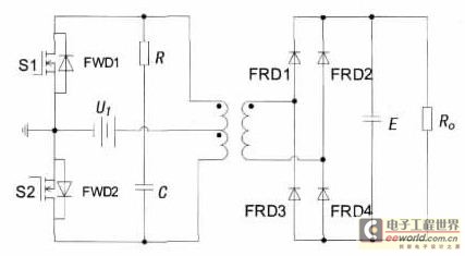
With the increase in the variety of modern electrical equipment for vehicles and the rise in power levels, there is a growing demand for different types of power supplies, including AC and DC sources. The power system needs to...
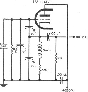
To update the fundamental oscillator circuits, simply replace the transistors with tubes. Alternatively, if one owns a vintage vacuum tube radio, it may be of interest to learn about historical practices. In general, the foundational principles of electronic circuits...

This document provides a step-by-step guide for modifying a disposable camera flash unit to serve as a power supply for a Geiger tube. The process involves removing the flash tube and trigger transformer from the circuit board by gently...

This circuit is a simple mixer circuit that can mix two signal channels into one output channel. It utilizes a codec circuit to convert stereo audio into mono audio. Additionally, the circuit can increase the number of channels by...

The circuit consists of a triggering device, a monostable delay circuit, an alarm sound generator, an audio amplifier circuit, and a light control circuit, with a partially blocking preset circuit and power circuit. When the door is locked and...