
Using FET 2n3819 simple audio mixer circuit

This mixer circuit is designed to combine two audio signal channels into a single mono output, making it suitable for various audio applications where space and power consumption are critical. The codec circuit serves as the primary component for converting stereo signals into a mono format, ensuring that the output is compatible with mono audio systems.
The addition of variable resistors VR1 and VR2 allows for fine-tuning of the audio levels from each input channel, providing flexibility in balancing the audio mix. Resistor R1 and capacitor C1 can be used to adjust the frequency response or gain of the circuit, depending on the specific requirements of the application. The circuit's low power consumption is advantageous for portable devices powered by 9-volt batteries, ensuring extended operation without frequent battery replacements.
When the audio signal enters the circuit, it is first coupled through capacitors C1 and C2, which serve to block any DC offset and allow only the AC audio signal to pass through. This coupling is critical in preventing distortion and ensuring that only the desired audio frequencies are processed. The signals are then directed to the variable resistors, where the user can adjust the volume levels before they reach the FET Q1.
The FET (Field Effect Transistor) Q1 acts as an amplifier, boosting the audio signal to a usable level for output. After amplification, the signal is sent through capacitor C3, which again serves as a coupling capacitor to ensure that any DC component is blocked from reaching the output stage. This final coupling stage is essential for maintaining signal integrity and ensuring that the output is clean and free from unwanted noise.
Overall, this simple mixer circuit is an effective solution for combining audio signals while maintaining low power consumption and allowing for user-adjustable audio levels. Its design is suitable for various applications, including portable audio devices, DIY audio projects, and other scenarios where space and power efficiency are paramount.This circuit, a simple mixer circuit. It can mix two signal channels and one channel is output. Using a codec circuit, Convert stereo audio to mono audio time. It can increase the number of channels too. By adding a VR1, R1 and C1 to the amount needed. Then connected to Buffett a new one. Most importantly is eating circuit current is very low. Can use with 9-volt batteries immediately. When entering voice signal, one of input 1 and input 2. Audio is via C1 and C2 of each channel, served coupling signals to VR1 and VR2. To adjust the audio to the Fet Q1. Which it serves, including audio. Then expand signal the output pin S through C3 For coupling signal again, before leaving to the output. 🔗 External reference
Related Circuits
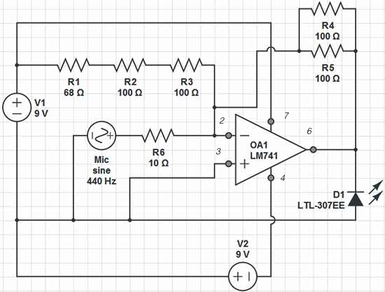
Red = V+, Black = V-, Green = GND, Yellow = Mic Input, Orange = LED Output. The op-amp used is an LM741, which is intended to adjust the peak brightness of the LED based on the ambient sound...
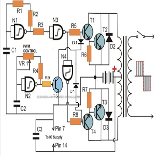
The PWM-controlled modified sine wave inverter circuit presented here utilizes a single 4093 integrated circuit (IC) for its specified functions. This IC consists of four NAND gates, with two configured as oscillators and the other two serving as buffers....
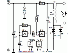
The circuit is designed for conducting safe experiments with high-voltage pulses and operates similarly to an electrified fence generator. This circuit is engineered to generate high-voltage pulses suitable for educational purposes and experimentation. The design is inspired by electrified fence...
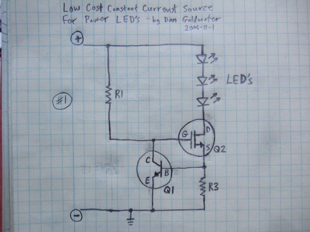
Here is a simple and inexpensive ($1) LED driver circuit. The circuit functions as a constant current source, ensuring that the LED maintains consistent brightness. The LED driver circuit is designed to provide a stable current to the LED, which...
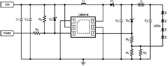
The LM3410 constant current LED driver is a monolithic integrated circuit that enables the design of high-efficiency, low-cost lighting solutions using a minimal number of electronic components. It employs current-mode control and internal compensation to ensure optimal performance across...
To determine the loudness of different headphones, one must calculate the power delivered to each headphone based on the source impedance. It is likely that the source impedance is closer to 32 ohms than to 250 ohms, suggesting that...