
RS-232 to 100 MHz RF adapter

The described system operates within the FM broadcast band at 100 MHz and serves as a low power, low bandwidth data signaling system. The design includes a transmitter and receiver that facilitate communication between a terminal and various peripherals located on the same desktop. The terminal connects to the system via an RS-232 interface, allowing keystrokes to be transmitted wirelessly through the RF data channel. The flexibility of the system is highlighted by the ability to set and change transmit and receive addresses, which are stored in EEPROM, enabling the terminal to interact with multiple devices in a straightforward manner.
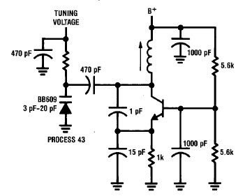
The circuit requires careful tuning of both the transmitter and receiver coils to achieve optimal performance at 100 MHz. This tuning process involves stretching or compressing the coils and may utilize simple tools for adjustment. The transmitter should first be tuned using an FM broadcast receiver, followed by the receiver, which can be adjusted based on the signal output from the transmitter. The tuning of the receiver can be monitored using an oscilloscope or a peak detector circuit, which aids in identifying the most negative peak of the received signal.
Additional tuning techniques include the use of a high impedance voltmeter or an earphone coupled to the op amp's output to facilitate the tuning process. The tuning process may require patience and careful adjustments to avoid overshooting the optimal tuning point. A variable capacitor can be incorporated to simplify tuning further.
Overall, this system represents a practical solution for low bandwidth wireless communication on a desktop environment, allowing for the integration of multiple microcontroller-based devices while adhering to legal regulations regarding unlicensed transmitter operation. This section describes an experimental low power, low bandwidth data signaling system that operates at 100 MHz (In the FM broadcast band in the U.S.). Before operating a radio transmitter, find out what kind of transmitter operation, if any, is permitted in your locality.
Radio transmitter operation is a serious legal matter. In the United States, operation of unlicensed intentional radiators is covered by Part 15 of Title 47 of the Code of Federal Regulations. This design can be readily adapted to different frequencies and different power levels. If you choose to build and operate the transmitter described here, you do so at your own risk. I'm only publishing this as an example of what can be done, and to show how easy it is to build a simple but functional receiver.
This is an adapter that allows a terminal to communicate via a 100 MHz data channel with peripherals on the same desk top. Keystrokes from the terminal are are received through the RS-232 connection and sent through the 100 MHz RF data channel.
See the page, Digital Wireless for the Desktop, on this site, for the basics of the transmitter, receiver, and data format. The reason I made this was to make a simple method of switching between instruments on my desktop. I was staring to accumulate a number of microcontroller-based devices that I want to be able to switch my computer among quickly and this provided the simplest desktop networking solution I could think of.
Any data received over the 100 MHz RF data channel addressed to the terminal is decoded and sent to the terminal. The transmit and receive address of the terminal is set by the user and stored in EEPROM. The address field has a range of 0..7, and the transmit and receive address can be changed by entering an escape sequence.
The sequence{
This simplifies things a lot because only the transmit address will have to be changed. There are two adjustments on this board. The coils for the transmitter and receiver need to be stretched or otherwise deformed to tune it to 100 MHz. Using an FM broadcast receiver turned to 100 MHz, adjust the transmitter first. The receiver can then be adjusted using a transmitter as a signal source. Adjustment of the coils is quite critical, so use a pair of small (or pointy) dieletric instruments (in this case, I used two bamboo sticks, one with a sharp point, and the other carved to resemble a screwdriver blade.
Find out where the transmitter is transmitting by tuning around the FM band. Once you find it, you can increase the transmitter's frequency by stretch in the coil, and lower the frequency by compressing the coil. Patiently stretch and squeeze the coil until it is tuned to 100 MHz. As for tuning the receiver, the quickest and easiest method is to use an oscilloscope to monitor the output of the first op amp in the receiver (pin 1 in the schematic on this page) and tune for the most negative peak of the data signal from the transmitter.
Lacking an oscilloscope, a peak detector like the one featured on this site (See Precision Audio Frequency Peak Detection Probe on this site) can be used to monitor the most negative peak. A reasonable substitute for this purpose can be built by connecting a PNP emitter follower to the output of the first op amp (where the signal is still analog), grounding the collector, and use a 100K resistor from the emitter to the positive power supply and a 10 uf capacitor from the emitter to ground.
This makes a negative peak detector for signals above ground. Monitor the voltage across the capacitor with a high impedance voltmeter set to 2 volts full scale and patiently tune for the lowest output voltage. You might have to reposition the transmitter with respect to the receiver as you get the receiver tuned in so as to have a large enough signal to observe on the meter but so large that it makes the receiver clip the signal.
I tried this and found it to work very well. Capacitively coupling a high impedance earphone to the op amp's output also helps to get the receive into the right range quickly (tune for loudest signal on the earphone then fine tune using the meter.) There is some art to doing the actual tuning, like returning your hands and arms to the same position and keeping them very still after each adjustment while you wait for the circuit to settle so you can see the result of the adjustment. Be patient and also be aware that if you change the coil too much at one time, you might go past the point of optimum tuning and you may have to compress the coil and back up a bit.
If you don't mind putting in the extra parts, a variable capacitor or voltage variable capacitor would make this a lot easier. Note that you will have to use a clip lead or jumper to keep power on the circuit while tuning it up, unless you happen to have the RS-232 connector plugged into a computer.
You can also tune up the receiver without any kind of tuning meter, but it takes a lot more patience. Operate a transmitter continuously. Position the receiver near the transmitter and adjust the coil in the receiver until the signal is decoded by the receiver.
Then, move the receiver further away until the decoder stops working and retune until it starts working again. Continue until no further improvement can be found. This is tedious but it saves the expense of a trimmer capacitor on each board -and that is an alternative.
🔗 External reference
Related Circuits
The original TX was designed to be only PULSE Modulated for a proportional R/C system, but I later used the same circuit to make an HF bands Amplitude Modulation (AM) transmitter using PA-Base Modulation. It eliminated the need for...
A simple high-efficiency Colpitts oscillator is utilized in higher frequency ranges, specifically above 50 MHz. Colpitts oscillators are preferred as stray circuit capacitance is in parallel with the desired feedback capacitance, preventing undesirable spurious resonances that may occur with...
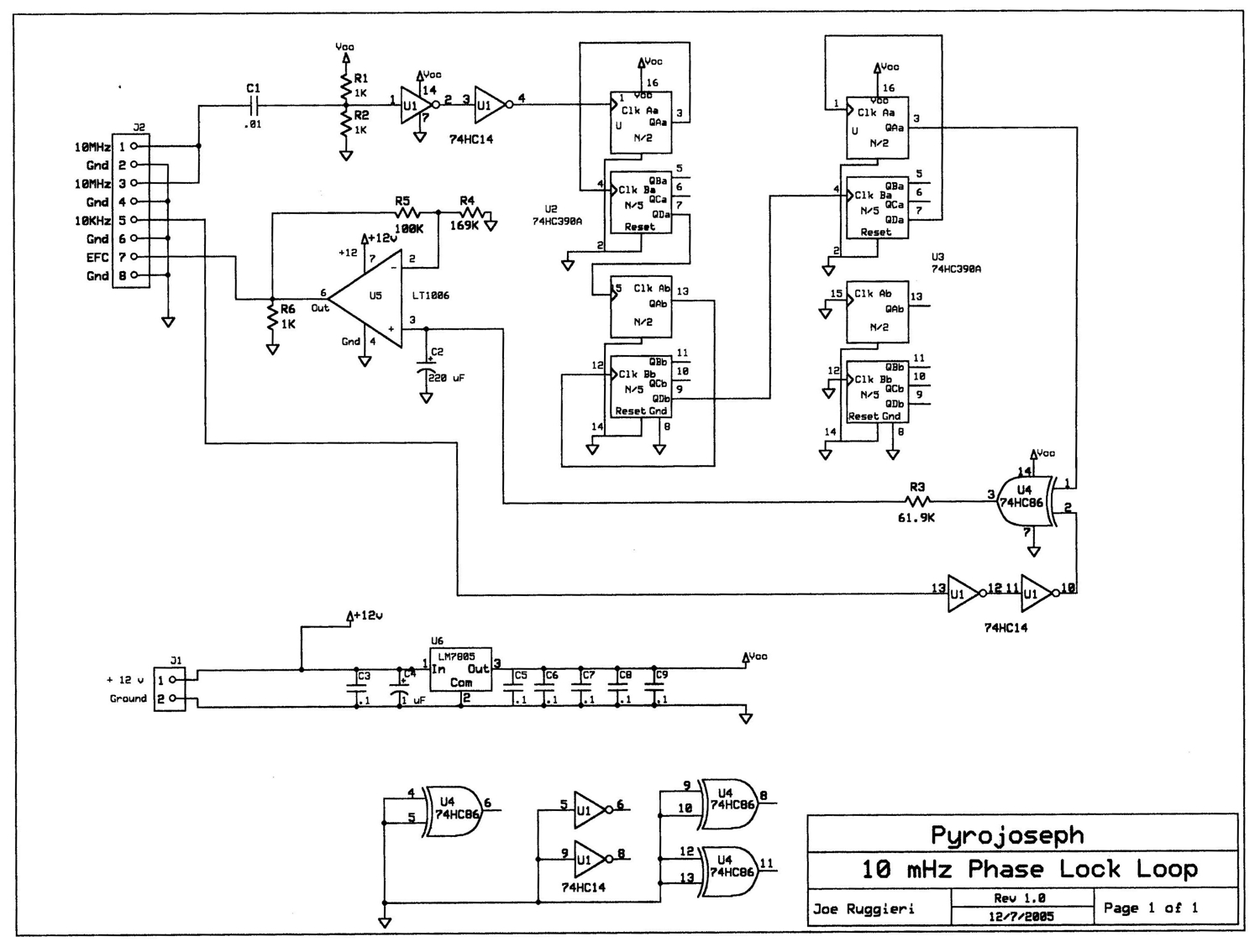
The block diagram illustrates that a 10 MHz signal is generated by an oven-stabilized 10 MHz crystal oscillator, which is locked to a precision 10 kHz signal produced by a GPS receiver module through a phase-locked-loop (PLL) circuit. In...
Construct this circuit using any preferred method, ensuring that high voltage safety measures are strictly adhered to. Proper insulation is crucial, and bare conductors must be spaced at least 2mm apart to avoid arcing. This circuit functions as a...
This circuit includes a 220µF capacitor and two diodes designed to slow down the switch-on process, thereby minimizing the output thump that occurs as the output capacitor charges through the speaker. While this feature is not essential and may...
This circuit generates a low power test signal and should not be used as a transmitter. Make sure you are within the law in the locality in which you operate this. As this was built from parts laying on...