
4 MHz Modulated Oscillator (2N4401)
")
Output level can be raised by biasing the audio amplifier's output stage to a higher voltage. This can be accomplished by placing a resistor from the base of the grounded-emitter transistor to ground. As the voltage to the oscillator is increased, the voltage swing required to achieve a given level of modulation must also be increased.
The gain of the audio amplifier is determined by the ratio of the 1 kΩ input resistor to the 56 kΩ feedback resistor, and is limited by the open-loop gain of the grounded-emitter stage. The open-loop gain can be estimated by examining the voltage drop across the 1 kΩ collector resistor. The voltage gain will theoretically be about 38 times the voltage across the 1 kΩ collector load. Thus, a 2-volt drop would yield an open-loop gain of approximately 76:1 at audio frequencies, making the closed-loop gain predominantly influenced by the feedback as described.
The low-frequency roll-off of the input signal is approximately calculated as 1/(2π × 3.3 μF × 1,000 Ω), resulting in a cutoff frequency of about 50 Hz. The input impedance of the amplifier at the summing node is sufficiently low to allow for the assumption of zero ohms as adequate for designs utilizing 5% resistors.
This circuit is designed to operate within a specific frequency range, and care should be taken to ensure that components are selected appropriately for the desired application. The overall design emphasizes flexibility in component choice, allowing for variations while maintaining functionality. Proper handling of the RF output and adherence to local regulations regarding emissions are critical for safe operation.This circuit generates a low power test signal and should not be used as a transmitter. Make sure you are within the law in the locality in which you operate this. As this was built from parts laying on the bench, it isn't optimized, but it does demonstrate that it is very tolerant of component choice. A lot of small signal transistor will work. Look up the 2N4401 -its not that special. Be aware that the antenna has DC on it and shorting the antenna to ground might destroy some of the parts.
You can use a small (.001 uf for example) capacitor in series with the oscillator output if you want. If you use an antenna with this device, make is a really short one as RF emissions are regulated in most if not all countries.
Besides, the waveform is pretty rich in harmonics. A while back I needed an amplitude modulated signal source at 4 MHz. This circuit was literally thrown together with parts laying on the bench. I built it dead bug style on a piece of copper clad board. It should work for you with little or no modification, other than the selection of the crystal, for use at other frequencies. At lower frequencies you might have to increase the capacitor values to get it to oscillate, and at higher frequencies, you might have to reduce the capacitor values a little.
Just be aware that the crystal will be operating in its fundamental mode. Overtone crystals will work, but they will oscillator at their fundamental frequency. Output level can be raised by biasing the audio amplifier's output stage to a higher voltage. This can be accomplished by placing a resistor from the base of the grounded-emitter transistor to ground. As voltage to the oscillator is increased, the voltage swing to achieve a given level of modulation will have to be increased as well.
The gain of the audiio amplifier is determined by the ratio of the 1 K ohm input resistor to the 56 k Ohm feedback resistor, and is limited by the open loop gain of the grounded-emitter stage. The open loop gain can be estimated by looking at the voltage drop across the 1 K ohm collector resistor.
The voltage gain will be (in theory) about 38 X the voltage across the 1 K collector load. Thus, a 2 volt drop would give you an open loop gain of about 76:1 at audio frequencies, so the closed loop gain will be dominated by the feedback as described above. The low frequency roll-off of the input singal will be approximately 1/(2Pi*3.3 uf * 1,000 Ohms ), which comes out to about 50 Hz.
The input impedance of the amplifier at the summing node is sufficeintly low enough to allow as assumption of zero ohms to be sufficient for a design using 5% resistors . 🔗 External reference
Related Circuits
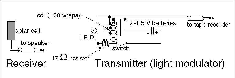
Electromagnetic radiation is utilized in communication systems. Common forms of electromagnetic radiation include radio waves, microwaves, and television signals. Visible light, which is also a type of electromagnetic radiation, can be employed for signal transmission, leading to the development...
This FM 88-108 MHz radio amplifier is equipped with a BLF 245 and can be used with a heatsink from a processor and a cooler. The BLF 245 datasheet can be downloaded. The FM 88-108 MHz radio amplifier utilizing the...
A widely recognized circuit is the Hartley oscillator, which is characterized by a tapped coil within the LC tank circuit. The tap point of the coil is grounded. The oscillator's amplifier section functions as a common-emitter amplifier, resulting in...
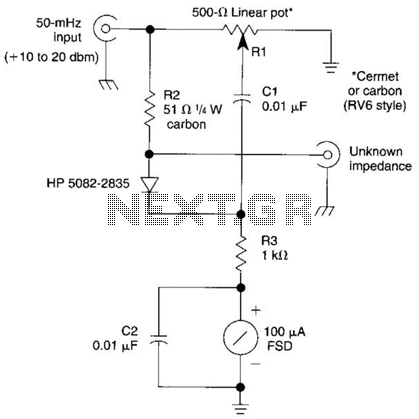
The bridge shown was used for measurements on 50-MHz amateur radio antennas. Rl is a miniature 500 linear potentiometer. The unknown impedance is compared to R2, a 51-ohm resistor. An external signal source is required. The described bridge circuit is...
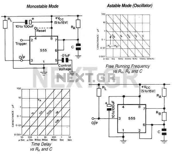
The 555 is a highly stable device for generating accurate time delays or oscillation. Additional terminals are provided for triggering or resetting if desired. In the time delay (monostable) mode of operation, the time is precisely controlled by one...
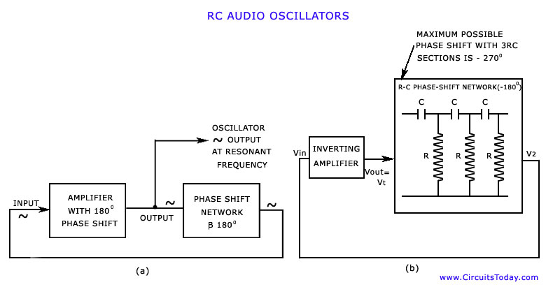
The discussion has focused on oscillators that utilize L-C tuned circuits, which create a 180° phase shift due to inductive or capacitive coupling, in addition to another 180° phase shift produced by the transistor itself. These L-C oscillators are...