
Rustl3rs Custom Smart LED Light

The electronic circuit is designed to control a lighting system for an aquarium, utilizing a combination of AC and DC power sources. The primary power source is a 120VAC plug, which feeds into a transformer that converts the AC voltage to a 12V DC output. This 12V supply powers several components, including operational amplifiers, timers, and relays. The operational amplifiers are critical for processing the voltage signals, allowing for precise control over the lighting system.
The timers provide the ability to automate the lighting schedule, enabling features such as sunrise and sunset simulation. When Timer 1 is activated, it triggers the operation of a cooling fan, which is essential for maintaining optimal temperature conditions for the LEDs. The fan's operation helps prevent overheating, ensuring the longevity and efficiency of the lighting system.
The capacitor in the circuit plays a vital role in the dimming functionality. It charges at a controlled rate, allowing the operational amplifier to read the voltage level and amplify it to the necessary range for the ELN-60-48D power supply. The slow charging of the capacitor ensures a gradual increase in brightness, mimicking natural light conditions. Once fully charged, the output can reach maximum brightness when the potentiometer is adjusted to its highest setting.
The circuit's design includes three operational modes: Regular, Off, and Override. The Regular mode allows for the gradual transition of light levels, simulating a natural sunrise and sunset. The Off mode disables all power to the lighting system, while the Override mode provides immediate activation of the lights, useful in situations where instant illumination is required.
Understanding the interaction between AC and DC voltages is crucial for the operation of this circuit. The operational amplifier is designed to handle both types of voltage, allowing it to function effectively within the system. The presence of AC voltage in conjunction with DC components raises questions about the circuit's modulation techniques, particularly regarding pulse width modulation (PWM) for dimming control. PWM is a technique used to vary the power delivered to the LEDs, enabling fine control over brightness levels while maintaining energy efficiency.
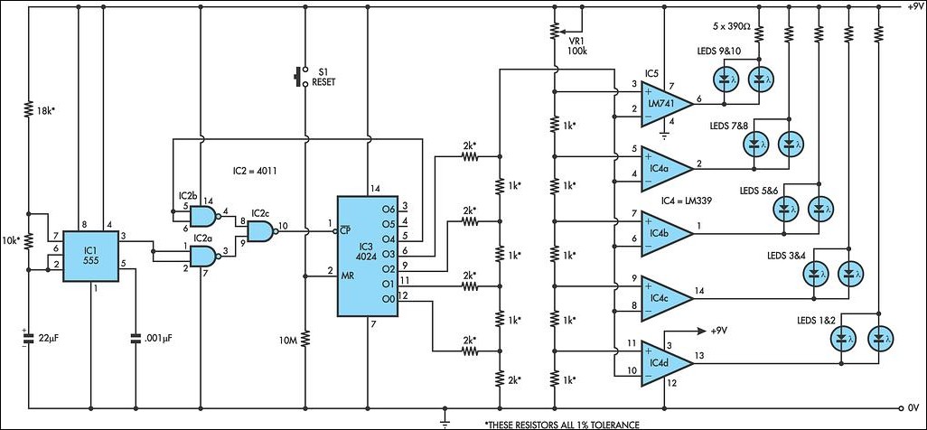
In summary, this circuit exemplifies a sophisticated approach to aquarium lighting control, integrating various electronic components to achieve automated and customizable lighting solutions. The blend of AC and DC power management, along with the operational amplifiers and timers, provides a comprehensive system capable of meeting the dynamic needs of aquatic environments.Those drivers could run fourteen leds but just went with twelve. This means that i could add 12 leds to mine with no extra drivers. Not that i will do that now but if my tank gets bigger (honey i swear the tank has been growing from day one you just havent noticed until now) i can add 12 without a driver. Cool. When reading these things, Start from Left to right. You can see that on the far left this whole device is powered from a 120VAC plug. From there a bunch of devices attach to that source: the 12V wall wart, the 2 timers, and the two power supplies that power the LED`s. Lets move on to whats powered by the 12V 500mA supply. The 12V supply powers the Operational Amplifiers at all times (the triangle things). the 12V is also run through the relays of the modified timers I`m using. After this point the 12 power is switched on or off by what I set in the timer settings. Lets assume the timers are on right now and only focus on what is going on when Timer 1 is on. When timer 1 is on, the 3" fan is now running. This will ventilate the light system and keep it cool. Also, when the switch is in "Regular Mode. " A capacitor starts charging up at a slow rate. The opamp (triangle) reads this voltage and amplifies it to achieve the proper 0-10V range needed by the ELN-60-48D power supply.
After 45 minutes, the capictor is fully charged and the ELN output is at 100% when the potentiometer (variable resistor: 5Kpot) is turned all the way up. If this is turned back a bit, the max votage the ELN sees is reduced. This allows me to manually dim while still having a sunrise/sunset. Another thing. this circuit has three switch settings. Regular: with sunrise and sunset, Off, and Overide: this overrides the sunrise sunset for an instant on, good for times when you need the lights on ASAP.
Feel free to ask any questions you want. I can also go over certain parts of the circuit in high detail. Including how I modified the timers and how I got the capacitor to take so long to charge up. I read schematics everyday, that one went over my head tho. interesting tho i like it. i been kinda bored with the ones i see everday anyway. So the voltage that actually does the dimming is AC this is what gets me i am used to looking at all DC schematics. i just dont understand what is the same and what is not. The opamp i see it has Ac voltage + - and DC V +-. I have the need to understand these things. what are they. Also where are these capacitors. So i see the AC source. then it goes to a transformer for a dc supply. then the timer. then the cap. then the opamp. then the driver. why is there ac voltage supplied to the opamp. And where does the pulse width modulation come in or are these not controlled with duty cycle 🔗 External reference
Related Circuits
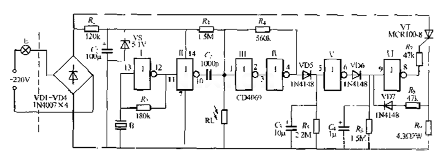
The circuit is designed for sound and light control of stairway and walkway lighting. It features high immunity and includes soft-start and over-current protection mechanisms. During the day, the photosensitive resistor has low resistance, resulting in a low voltage...
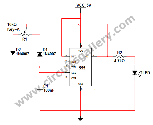
How to change the brightness of an LED. Are LED lights dimmable? Is it possible to adjust the brightness of LEDs? An LED is essentially a diode; when the forward voltage exceeds 0.7 volts, it begins to emit light,...
Christmas is approaching, and it is the time of year when electronics students and hobbyists consider creating a Christmas circuit for their homes, particularly one that features flashing lights. Numerous circuits and kits are available that can flash various...
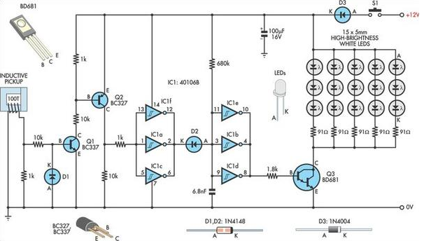
A useful timing strobe can be constructed using high-brightness LEDs and a few common components. Ignition pulses from the number 1 cylinder high-tension lead are used to trigger the circuit via a homemade inductive pickup. Transistors Q1 and Q2...
This LED circuit replicates the initial LED sequence currently utilized by FISA for Formula One racing. It can also be employed with slot car sets, such as HO scale AFX, Life Like, or Tyco sets, or used in communication-controlled...
The circuit utilizes the LM324 low-power operational amplifier, which consumes approximately 3mA of current. This low current draw ensures that the battery will not be adversely affected if the circuit remains connected for extended durations. The LM324 is a quad...