
SAA1057 PLL Synthesized FM Transmitter

The circuit utilizes the MICROCHIP PIC16F84 microcontroller, which serves as the central processing unit, managing inputs from buttons and controlling the output to a 2-line, 16-character LCD display. The microcontroller is programmed to handle user interactions and display relevant information on the LCD, facilitating user-friendly operation.
The PLL circuit, SAA1057, is integrated into the design to provide frequency synthesis and demodulation capabilities. This allows the system to lock onto specific frequencies, enhancing signal stability and quality. The VCO, implemented with transistor Q8, is a critical component that generates the necessary oscillation for the PLL operation. The inclusion of two BB109 varactor diodes allows for voltage-controlled tuning, enabling the VCO to adjust its frequency in response to varying control voltages.
Transistor Q7 functions as a buffer, effectively isolating the VHF signal to prevent loading effects that could degrade signal integrity. This buffering is crucial for maintaining the performance of the circuit, as it ensures that the VHF signal is split appropriately for further processing. One branch of the signal is directed towards transistor Q9, which may be responsible for amplification or further signal processing, depending on the overall design requirements.
In summary, the described circuit combines a microcontroller, a PLL, a VCO, and various transistors to create a robust system capable of handling VHF signals while providing user interaction through buttons and an LCD display. The careful selection of components and their configurations ensures that the circuit operates efficiently and reliably in its intended application.The functioning of all is provided by a microcontroller from MICROCHIP PIC16F84 which provides support for buttons, LCD 2 lines of 16 characters and the circuit pll SAA1057. The VCO is entrusted to the transistor Q8 associate of his two diodes varicaps BB109, a floor buffer Q7 separates the VHF signal obtained in two ways, on the one hand to Q9 to ensl..
🔗 External reference
Related Circuits
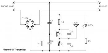
This circuit connects in series with a home phone line and transmits phone conversations through the FM band whenever the telephone handset is picked up. The transmitted signal can be tuned by any FM receiver. The circuit includes an...
This low-cost short-wave transmitter is tunable from 10 to 15 MHz using a ½J gang condenser (VC1), which determines the carrier frequency in conjunction with inductor L1. Frequency trimming is achieved with VC2. The carrier signal is amplified by...
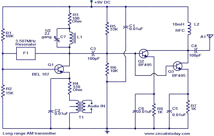
The circuit diagram of an AM transmitter circuit based on three transistors. With correct tuning and a matching antenna, the transmitter can effectively transmit amplitude-modulated signals. The AM transmitter circuit utilizes three transistors configured to amplify and modulate the input...
In 1896, Marconi successfully transmitted electromagnetic waves over a distance of approximately 3 kilometers. Shortly thereafter, he established radio communication across water between Lavernock Point in South Wales and Flat Holm Island. The transmitter utilized a spark inductor connected...
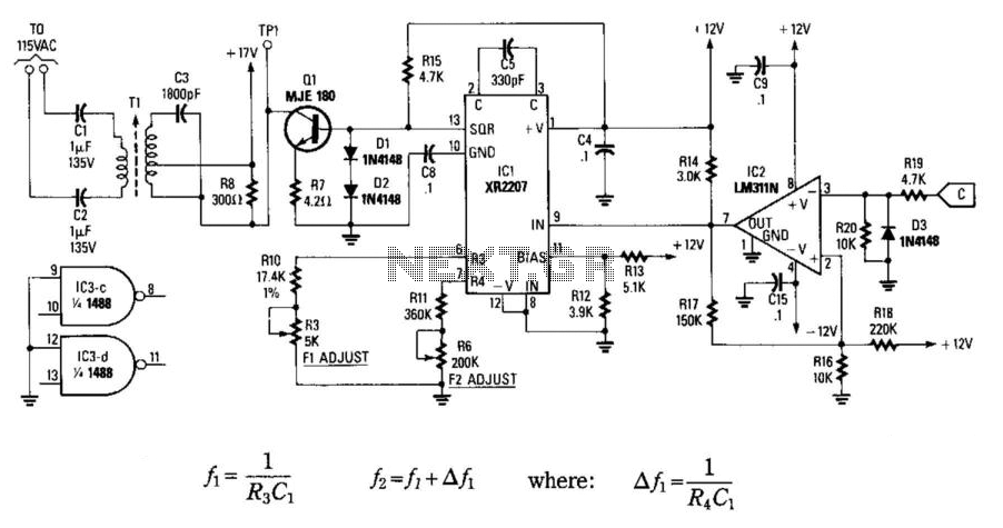
In this circuit, data at input C is amplified by IC2 and then fed to modulator IC1. IC1 generates two frequencies, depending on the values of C5, I10, R5, Rn, and R6. The frequency f1 is generated if pin...
The FM transmitter circuit operates within the broadcast band of 88 to 108 MHz and can be utilized to transmit audio signals for remote listening. The output power... The FM transmitter circuit is designed to function within the frequency range...