
Long range AM transmitter Using BF495 Transistor

The AM transmitter circuit utilizes three transistors configured to amplify and modulate the input audio signal. The first transistor acts as a microphone preamplifier, converting the audio signal into an electrical signal suitable for further processing. The second transistor functions as a modulator, where the audio signal is combined with a high-frequency carrier wave generated by an oscillator circuit. The third transistor serves as a final amplifier, boosting the modulated signal to a level suitable for transmission.
In this setup, proper tuning of the circuit is crucial for optimal performance. The oscillator frequency must be adjusted to match the desired transmission frequency, while the antenna must be matched to the transmitter's output impedance to maximize radiated power and minimize signal loss. Capacitors and inductors are typically used in the tuning circuit to adjust the frequency response and ensure that the transmitter operates within the appropriate bandwidth.
The circuit may also include additional components such as resistors for biasing the transistors, diodes for signal rectification, and filters to eliminate unwanted harmonics and noise. The overall design must adhere to relevant regulations regarding transmission power and frequency to ensure compliance with communication standards. Proper assembly and layout of the circuit are essential to minimize interference and maintain signal integrity during operation.the circuit diagram of an AM transmitter circuit based on three transistors. With correct tuning and a matching antenna, the transmitter can .. 🔗 External reference
Related Circuits
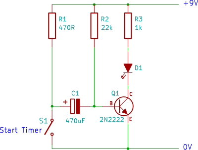
A single transistor timer circuit tutorial designed for beginners in electronics. This is an easy electronic circuit that can be constructed on a breadboard. The single transistor timer circuit utilizes a transistor as the primary switching element to create a...

The difference between instantaneous frequency and central frequency of the carrier is directly proportional to the instantaneous value of the amplitude of the message signal. A 555 Timer configured in Astable Mode can be utilized for generating Frequency Modulated...
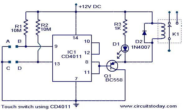
A simple touch switch circuit using the CD4011 is presented. The CD4011 integrated circuit (IC) is configured as a flip-flop. Pins 9 and 13 of the IC function as the set and reset terminals, respectively. CMOS ICs like the...
The simple FM radio circuit was overlooked during the transition from vacuum tubes to transistors. In the late 1950s and early 1960s, several construction articles were published on building a straightforward superregenerative FM radio. After extensive research into these...

This is a simple tone control circuit using the TDA1524A, which is a key component in this IC chip diagram from Philips. The circuit allows for tone control adjustments such as bass, treble, and balance, enabling users to fine-tune...
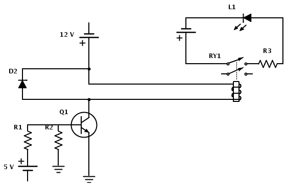
Create a circuit that enables the activation of a relay to control an LED. The relay operates at 12 V, while the available input voltage is 5 V. An NPN transistor will be utilized to switch the power to...