
Safety Guard

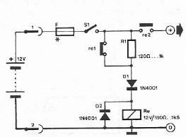
The time delay circuit is designed to safeguard sensitive electronic devices from immediate power surges that can occur when the power supply is restored. It operates by incorporating a delay mechanism that ensures a brief waiting period before the appliances are powered on. This delay allows any transient voltage spikes to dissipate, thus preventing potential damage to the connected devices.
The circuit typically consists of a relay, a resistor-capacitor (RC) timing network, and a diode for flyback protection. Upon receiving power, the RC network begins charging, and the time delay is determined by the values of the resistor and capacitor. Once the voltage across the capacitor reaches a certain threshold, it activates the relay, closing the circuit and supplying power to the connected appliances.
Additionally, a diode is placed in parallel with the relay coil to protect the circuit from back EMF generated when the relay is de-energized. This protection is crucial for maintaining the integrity of the control circuitry.
Overall, this time delay circuit is an effective solution for enhancing the reliability and longevity of home appliances by mitigating the risks associated with voltage spikes during power restoration.Protect your home appliances from voltage spikes with this simple time delay circuit. Whenever power to the appliances is switched on or resumes after mai.. 🔗 External reference
Related Circuits
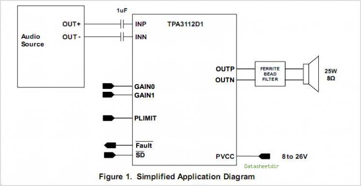
The TPS3803 and TPS3805 families of supervisory circuits offer circuit initialization and timing supervision, mainly for digital signal processors (DSPs) and processor-based systems. The TPS3803G15 device features a fixed-sense threshold voltage (VIT) determined by an internal voltage divider, while...
Locker Guard Circuit Diagram. This compact circuit is designed to protect a locker or almirah from burglary. If the locker is opened while in the armed state, the circuit triggers a loud police siren to deter the burglary attempt. The...

A flashing LED signals the necessity to water a plant. Very low current consumption - 3V powered circuit. This circuit is intended to signal when a plant is needing water. A LED flashes at a low rate when the...
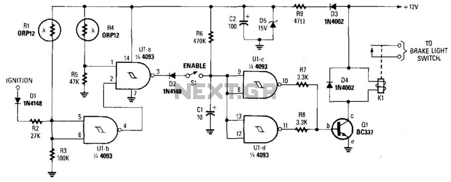
This circuit activates the brake lights of a parked car when headlights from an approaching vehicle are detected, alerting the driver of the oncoming vehicle about the stationary car. LDR4 serves as the sensor, while LDR1 deactivates the circuit...
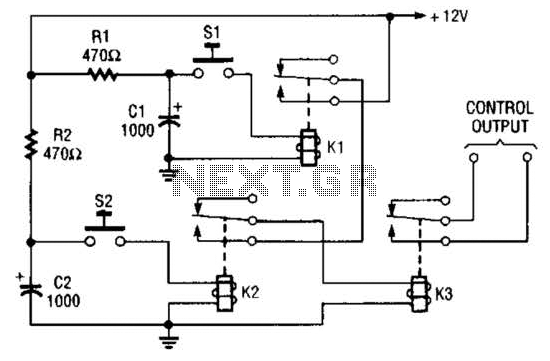
Due to the limited hold-on time of the delay circuits R1/C1 and R2/C2, both switches S1 and S2 must be activated simultaneously to energize the load. The circuit in question involves a delay mechanism governed by the time constants associated...
Safety polarity connection circuit design using common electronic components The safety polarity connection circuit is designed to ensure that electronic devices are connected with the correct polarity, preventing damage from reversed connections. This circuit typically employs common electronic components such...