
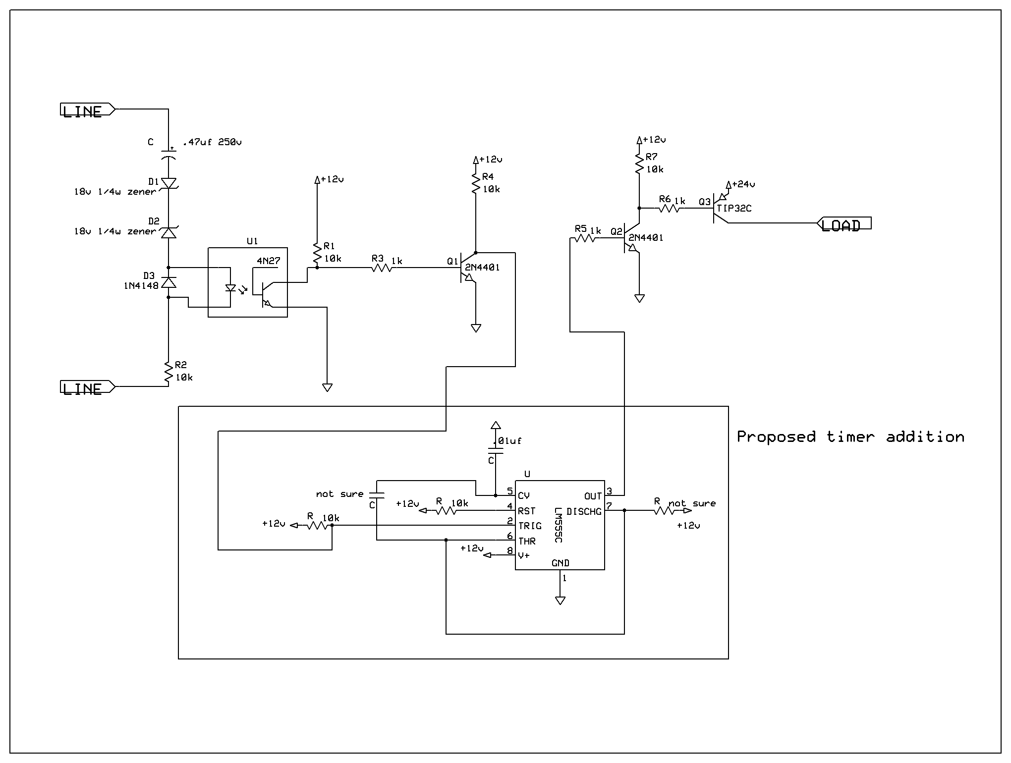
Safety polarity connection circuit

The safety polarity connection circuit is designed to ensure that electronic devices are connected with the correct polarity, preventing damage from reversed connections. This circuit typically employs common electronic components such as diodes, resistors, and transistors to create a protective mechanism.
The core of the circuit often includes a diode placed in series with the power supply. This diode allows current to flow in the correct direction while blocking reverse polarity. In addition, a second diode may be used in parallel with the load, oriented to conduct during reverse polarity conditions, thereby protecting sensitive components from damage.
Resistors can be incorporated to limit the current flowing through the diodes, ensuring they operate within safe parameters. Furthermore, a visual indicator, such as an LED, may be added to signal correct polarity. This LED would be connected in such a way that it illuminates when the circuit is correctly powered, providing immediate feedback to the user.
In more complex designs, a transistor can be utilized to enhance the circuit's functionality. For example, a transistor can be configured to act as a switch that disconnects the load in the event of incorrect polarity, adding an additional layer of protection.
Overall, the safety polarity connection circuit is a fundamental design that leverages widely available components to enhance the reliability and safety of electronic devices, making it an essential consideration in circuit design.Safety polarity connection circuit design using common electronic components 🔗 External reference
Related Circuits
A 12-volt relay is connected between two stages such that when it receives 12 volts from the supply, it activates and disconnects the 3-volt DC supply from the melody circuit. Conversely, when mains power is absent, the relay switches...
This circuit is designed to drive an ultrasonic transducer. A question has arisen regarding how to limit the output current, as a 60W transducer may be at risk of damage due to excessive current. Guidance or examples for integrating...
An efficient 4-stage stabilized power supply unit is designed for testing electronic circuits. This unit provides well-regulated and stabilized output, which is essential for most electronic circuits to yield accurate results. The circuit features audio-visual indicators to signal a...
This is a simple two-transistor lamp flasher circuit that can be used to flash a 6-volt lamp. The circuit is compact and can be easily fitted into a small enclosure. It utilizes two transistors: one is an NPN BC549,...
A ringer interface circuit is designed to buffer the output of a central telephone system, which connects to multiple ringers distributed throughout a building. This circuit addresses an issue where the line overloads when ringing, requiring a reset. The...
This circuit is primarily designed to provide a microphone input for standard home stereo amplifiers. Utilizing a battery supply effectively eliminates the risk of low-frequency hum interference from mains power, simplifying the connection to the amplifier by removing the...