
Sampling RF Power

For practical implementation, consider a scenario with a 300-watt transmitter requiring output power monitoring. Utilizing a 30 dB directional coupler reduces the output to 300 milliwatts at the sampled port. An additional 20 dB attenuator is then necessary to further reduce this level to 3 milliwatts. Based on the resistor values required, R1 and R3 should be approximately 61 ohms, while R2 should be around 248 ohms; using standard resistor values of 62 ohms and 250 ohms is acceptable. For monitoring reverse power with the same coupler and targeting a full scale equivalent to a 2:1 SWR, a 10 dB attenuator is sufficient, bringing the 30-watt reverse power down to 3 milliwatts after coupling. The recommended resistor values for this case are 96 ohms for R1 and R3, and 71 ohms for R2, with proximity to 100 ohms and 68 ohms being permissible. Alternatively, if only forward power monitoring or ALC signals are required, a simple method involves extracting a small amount of RF from the transmission line using a capacitor, probe, or resistor to feed into the detector circuit input.Perhaps you might want to provide a little ALC feedback to your driver, or use signals from a directional coupler to drive power monitors or SWR lockout circuits. I use this modest little circuit to do these things; the basic idea is to use a microwave diode pair as a detector/voltage doubler to sample the RF signal, and produce a useful DC level to feed
those other devices. At the front end is a chip resistor attenuator (R1, R2 and R3) to help put the detected RF at the most useful level for the diodes; then follow the whole thing with a low-pass filter. A trimmer resistor across the output provides some adjustment of the output level, as well as a load to make the response of the diodes reasonably linear (more on this in a bit).
The output has some bandwidth, which can be helpful for monitoring video or audio (AM). The circuit is wideband and useful throughout the VHF range to well above 3. 5GHz as shown; the useful range can be shifted down to HF and below by changing C1 to a larger value (1000pf). The circuit is set up to produce a negative output signal, which is the most commonly used polarity, though a positive signal can be produced by reversing the diode connections.
For power monitoring, it`s best to find a range of power where the diodes are most linear; for ALC feedback, this is not necessary, nor is it for necessary for SWR lockout circuits (both of these require only a relative output level). For power meters, custom meter scales are a must for absolute accuracy, but you can get close by adjusting the load (I used 5k here) and driving the circuit in a range of power that produces the best linearity.
I didn`t spend a lot of time fine-tuning the load, so more experimentation might produce even better results. This test data was measured in steps up to about 2. 5 milliwatts; above that level the output goes into compression, becoming even less linear; the same is true for levels below about 1/2 milliwatt (output drops off rapidly), so for power monitoring, it`s best to keep the input level to about 3mw max.
This will produce an output of more than a volt. For this particular diode type and load, the most linear response appears to be between levels 4 and 8. Instead of reversing the diode connections to produce a positive output, another option is to use a diode already packaged in reverse configuration, like this one.
Response is similar. OK, let`s go through an example showing how to set the power levels up for the detector; I have a 300w transmitter, and want to monitor the output power. I`ll be using a directional coupler to monitor the output, and it is a 30db coupler. This coupler will reduce the 300w by 30db at the sampled port, producing a level of 300mw. From there I need an attenuator that will reduce this level by another 20db, reducing the 300mw to 3mw.
Looking at the table to the right, I`ll need to use 61 ohms for R1 and R3, and 248 ohms for R2. I`ll use the resistors I have available. perhaps 62 ohms and 250 ohms. the values can vary somewhat, it just isn`t that important to miss by a few ohms. One more example. if you want to also monitor reverse power using the same coupler, and have full scale be equivalent to 2 to 1 SWR, this will be 10db down from the forward power level, or 30w. In this case, you`ll only need a 10db attenuator to do the job; 30w will be sampled down to 30mw at the coupler port, and 10db will drop this to 3mw.
The chart says to use 96 ohms for R1 and R3, and 71 for R2 (100 ohms and 68 ohms is close enough). Of course, you don`t need to use a directional coupler if all you need to do is provide forward power monitoring or an ALC signal; the simplest way to do this is to just pick off a bit of RF from the transmission line with a small capacitor, a probe, or a resistor, and feed it to the input of the detector circuit. The board show 🔗 External reference
Related Circuits
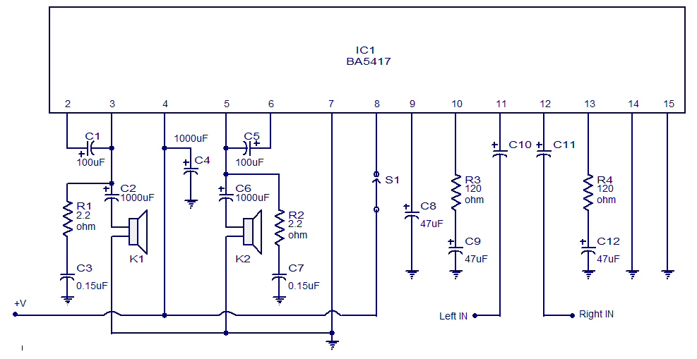
The BA5417 is a stereo amplifier integrated circuit (IC) that features several advantageous characteristics, including thermal shutdown, a standby function, soft clipping, and a wide operating voltage range. It can deliver 5 watts per channel into 4-ohm loudspeakers when...
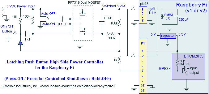
A momentary contact push button switch can be utilized to conveniently turn the Raspberry Pi (RPi) ON and OFF. Pressing the button will apply power to the micro USB header, maintaining power while the Raspberry Pi initializes and starts...
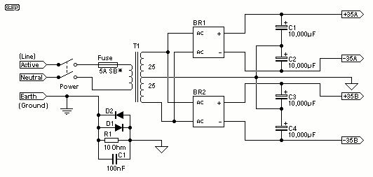
For the 60W amplifier, a nominal (full load) supply of +/- 35V is required, so a 25-0-25 secondary is ideal - however, see Updates, below. The circuit for the supply is shown below, and uses separate rectifiers, capacitors and...
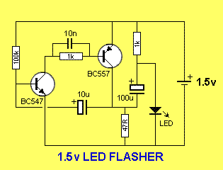
This is a simple 1.5V powered LED flasher circuit diagram. This circuit can flash 1.7V or 2.3V LEDs (depending on the color) using a 1.5V DC input. The LED will turn on when the 100µF capacitor is charged by...
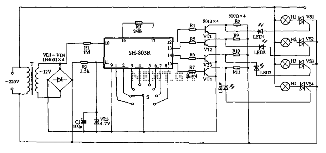
22V AC is supplied through thyristors VSl to VS4 for lighting control. The current is routed through transformer T, followed by rectification using diodes VD1 to VD4, and regulated by VD5 to provide a filtered output of approximately 4.7V...

The simple transistor tester in Figure 1 allows for the identification of the type of transistor and aids in detecting the emitter, collector, and base of the transistor. The simple transistor tester circuit is designed to facilitate the identification of...