
Transistor Tester Identifies Terminals Power

The simple transistor tester circuit is designed to facilitate the identification of transistor types (NPN or PNP) and to verify the functionality of the transistor's terminals: emitter, collector, and base. The circuit typically consists of a few key components, including resistors, a power supply, and a transistor socket for easy insertion of the device under test.
When the transistor is inserted into the socket, the circuit applies a small voltage to the base terminal, which allows for the determination of the transistor type based on its response. For an NPN transistor, a current will flow from the collector to the emitter when a positive voltage is applied to the base. Conversely, for a PNP transistor, the current will flow from the emitter to the collector when a negative voltage is applied to the base.
The circuit may also include an LED indicator that lights up when the transistor is functioning correctly, providing a visual confirmation of the transistor's operational status. Additionally, the use of multimeter probes can enhance testing capabilities, allowing for the measurement of voltage and current levels across the transistor terminals.
This simple tester is an invaluable tool for electronics enthusiasts and professionals alike, as it provides a quick and effective means to assess transistor functionality without the need for complex equipment. Proper understanding and usage of this circuit can lead to more efficient troubleshooting and repair of electronic devices.The simple transistor tester in Figure 1 lets you identify the type of transistor, and it helps in detecting a transistor`s emitter, collector, and base.. 🔗 External reference
Related Circuits
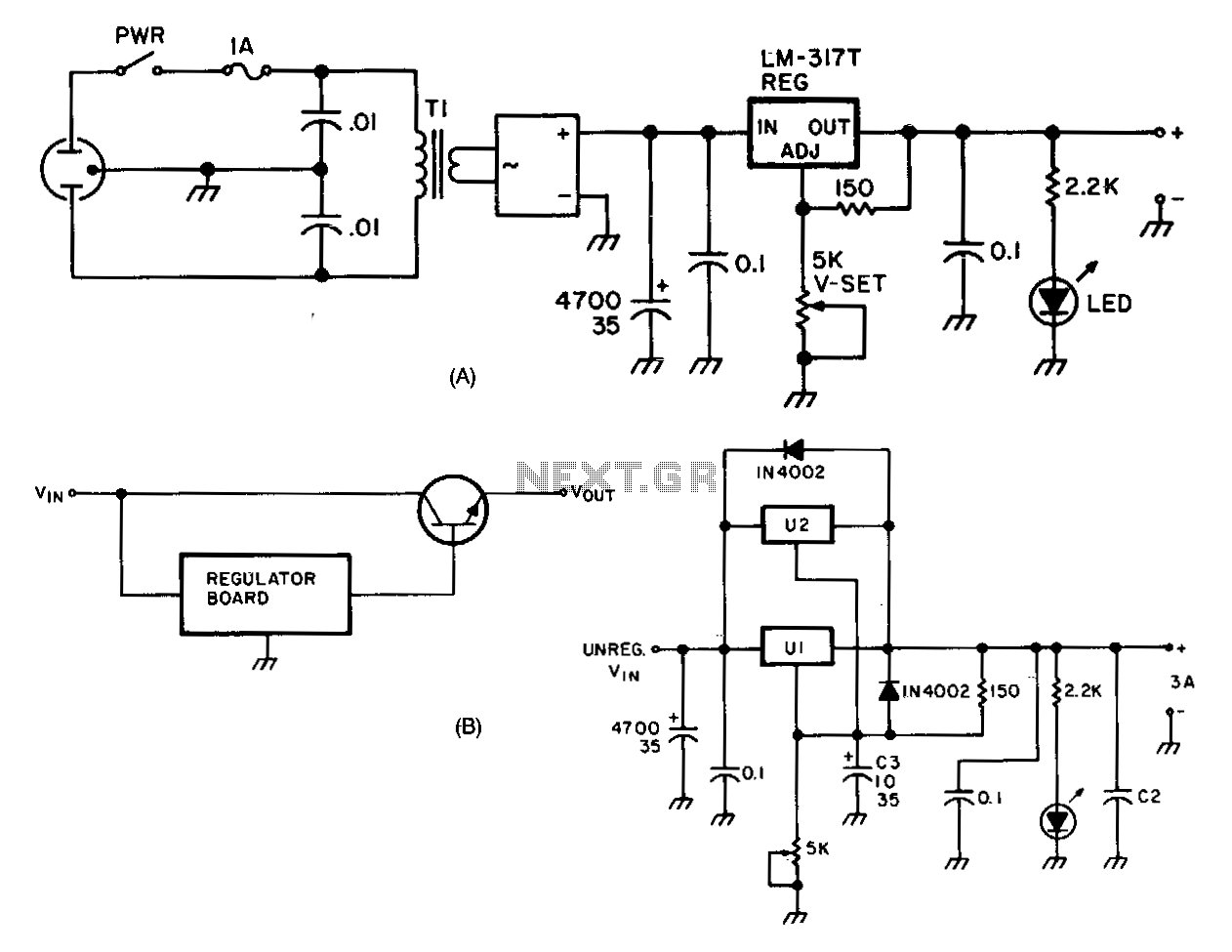
The LM317 adjustable regulator (U1) offers short-circuit protection and automatic current limiting at 1.5 A. The input voltage to the regulator is provided by a 4-A 100 PIV full-wave bridge rectifier (DB1). Capacitor C1 serves as the initial filtering...
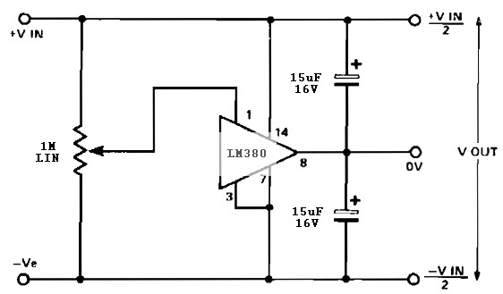
A simple split rail power supply based on the LM380 power supply. The design is intended to provide an inexpensive high-power supply, initially available in three power levels. A wide range of accessories is included to maintain an attractive...
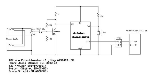
Have you ever wanted your home entertainment or sound system to power on automatically when plugging in your iPod or another portable MP3 player? To achieve automatic power activation of a home entertainment system when a portable device is...
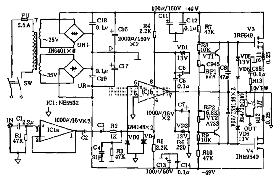
The amplifier circuit presented in this paper introduces a floating power supply aimed at increasing output power. The output power of the amplifier is influenced primarily by the final stage amplifier supply voltage. The circuit's principle is illustrated in...
This is a very simple, low-cost, Hi-Fi quality power amplifier. It can be built in five different configurations, as shown in the table, ranging from 20 W to 80 W RMS. The Hi-Fi quality power amplifier circuit is designed to...
The International Rectifier IRAM109-015SD is a multi-chip hybrid integrated circuit designed specifically for low-power appliance motor control applications, including fans, pumps, and refrigerator compressors. Its compact single in-line package (SIP-S) optimizes PCB space. The device includes several built-in protection...