
Sawtooth and Squarewave Oscillator

The described circuit involves a printed circuit board (PCB) with a control mechanism that allows for the adjustment of capacitance values. The specified capacitance values—100 pF, 470 pF, 0.001 µF (1 µF), 0.0022 µF (2.2 µF), 0.01 µF (10 µF), and 0.047 µF (47 µF)—are crucial for tuning the circuit to achieve specific frequency outputs.
Each capacitance setting corresponds to a set of measured frequencies, indicating that the circuit is likely part of a frequency generator or oscillator configuration. The frequencies listed suggest a range of applications, from audio signal processing to RF transmission, depending on the desired frequency output.
The variation in measured frequencies due to capacitor tolerances emphasizes the importance of selecting capacitors with appropriate specifications for precise applications. Capacitor tolerances can affect the stability and accuracy of the circuit, which may be critical in applications such as communication systems or audio equipment where frequency fidelity is paramount.
To create a comprehensive electronic schematic based on this description, one would typically include components such as capacitors, resistors, and possibly inductors, depending on the intended application. The schematic would illustrate the connections between these components and indicate how the control mechanism interacts with the capacitors to modify the output frequency. Additionally, it would be beneficial to include notes on the expected performance characteristics and potential sources of error due to component tolerances.
In summary, this circuit design highlights the interaction between capacitance and frequency, showcasing the need for careful component selection and adjustment to achieve the desired operational outcomes.With the Control "On the PCB", set at these Positions* CX = CW Center CCW 100 pf = 6, 400 hz 12, 050 hz 26, 000 hz 470 pf = 1, 525 hz 3, 200 hz 7, 232 hz. 001 uf = 681 hz 1, 425 hz 3, 250 hz. 0022 uf = 348 hz 619 hz 1, 540 hz. 01 uf = 69 hz 146 hz 340 hz. 047 uf = 16 hz 34 hz 88 hz. 1 uf = 7 hz 14 hz 34 hz These were Measured Freq uencies with "Typical" Capacitors. Due to Capacitor Tolerances, Your Results Will Vary a little. 🔗 External reference
Related Circuits
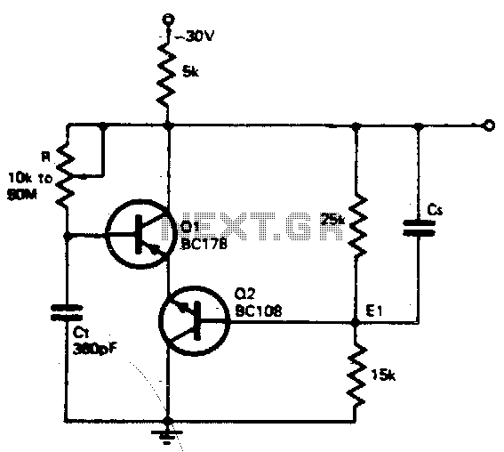
The timing resistor R can be adjusted to any value between 10 kΩ and 50 MΩ to achieve a frequency range from 400 kHz to 100 Hz. Connecting the timing resistor to the collector of Q1 ensures that Q1...

A Wien bridge oscillator generates sine waves with a very low distortion level. It produces zero phase shift at only one frequency (f = 1/2πRC), which becomes the oscillation frequency. Stable oscillation can only occur if the loop gain...
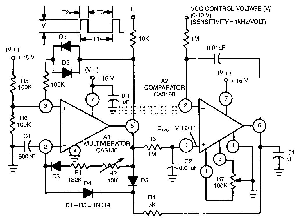
This circuit utilizes a CA3130 BiMOS operational amplifier as a multivibrator and a CA3160 BiMOS operational amplifier as a comparator. The oscillator exhibits a sensitivity of 1 kHz/V, with a tracking error of approximately 0.02% and a temperature coefficient...
The circuit serves as a foundational design, requiring experimentation for specific applications. In popular microwave bands, local oscillators (LOs) are typically generated using overtone crystal oscillators followed by multipliers. A table presents the standard LO frequencies for narrowband segments,...
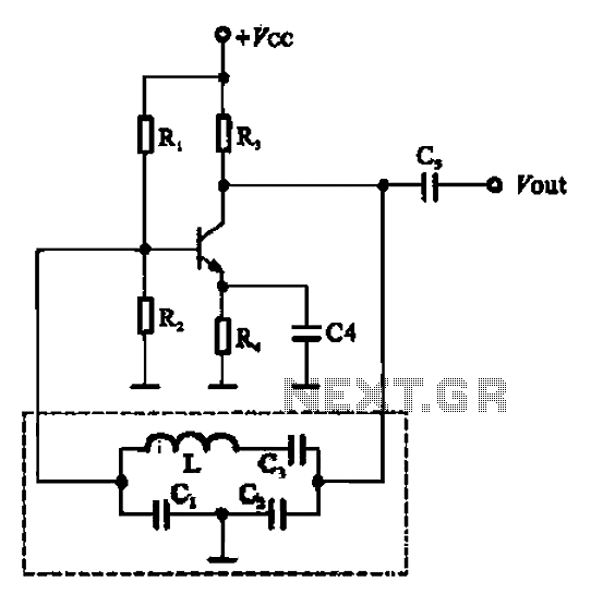
The Colpitts oscillator, based on the deformed oscillator principle, is formed by a Clapp oscillator. The fundamental differences between these oscillators lie in the resonant feedback circuit, which includes an additional capacitor C3 and inductors connected in series. Since...
A marker oscillator can be constructed using an NE555 timer to generate pulses at an audio frequency. This design facilitates the identification of signals amidst interference. The oscillator can utilize a crystal with a frequency ranging from 1 to...