
Audio Oscillator

The Wien bridge oscillator is a type of electronic oscillator that produces sine wave signals, characterized by its low distortion and stability. The fundamental principle of operation relies on the balance of a resistive-capacitive (RC) network, which sets the frequency of oscillation. The equation f = 1/2πRC reveals that the oscillation frequency is inversely proportional to the product of resistance and capacitance in the circuit.
In this oscillator design, a small lamp is employed to provide automatic gain control. As the output signal varies, the temperature of the lamp changes, which in turn alters its resistance. This feedback mechanism is crucial for maintaining the loop gain at unity, ensuring that the oscillations remain stable. The use of a lamp with a positive temperature coefficient allows for a self-regulating system, where increases in output power lead to increased resistance, thereby reducing gain and preventing distortion.
The oscillator is designed with four distinct frequency bands, enabling operation across a wide range of frequencies from 15 Hz to 150 kHz. This versatility is achieved through the use of ganged 20 kΩ potentiometers, which allow for fine-tuning of the frequency within each band. The circuit's low power consumption of approximately 4.0 mA from a 9-V battery makes it suitable for portable applications.
The output voltage of the oscillator, when loaded with a 10 kΩ resistor, is maintained between 4 to 5 V. The feedback resistor (RF) is strategically set to about 5% below the clipping threshold to optimize performance and minimize distortion. The output is taken from the center arm of a 5 kΩ potentiometer, which serves as an adjustable output terminal.
For interfacing with DC circuits, it is recommended to include a coupling capacitor in series with the output lead. This capacitor blocks any DC component while allowing the AC sine wave to pass through, effectively isolating the oscillator from the connected circuit and preventing any undesired interaction. This design consideration is essential for applications where the sine wave needs to be fed into subsequent stages without affecting the DC operating point of those stages.A Wien bridge oscillator produces sine waves with very low distortion level. The Wien bridge oscillator produces zero phase shift at only one frequency (f = 1/2 P RC) which will be the oscillation frequency. Stable oscillation can occur only if the loop gain remains at unity at the oscillation frequency. The circuit achieves this control by using the positive temperature coefficient of a small lamp to regulate gain (RF/RLAMP) as the oscillator attempts to vary its output. The oscillator shown here has four frequency bands covering about 15 Hz to 150 kHz. The frequency is continuously variable within each frequency range with ganged 20 k ohm potentiometers.
The oscillator draws only about 4. 0 mA from the 9-V batteries. Its output is from 4 to 5 V with a 10 k ohm load and the RF (feedback resistor) is set at about 5% below the point of clipping. As shown, the center arm of the 5 k ohm output potentiometer is the output terminal. To couple the oscillator to a dc type circuit, a capacitor should be inserted in series with the output lead.
(Texas Instruments, Linear and Interface Circuits Applications, Vol 1, 1985, p. 3-15 and 3-16. ) 🔗 External reference
Related Circuits
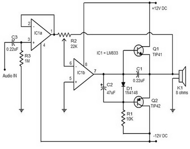
The 15W Class B audio amplifier circuit presented here is a straightforward Class B audio amplifier utilizing the TL082 operational amplifier, along with TIP41 and TIP42 transistors. The LM833 is a dual amplifier known for its high scanning speed...
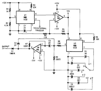
When this circuit is connected to a filter and an oscilloscope, the oscilloscope displays the filter's frequency response. A frequency that sweeps from low to high is applied to a filter. The oscilloscope is triggered by the start of...
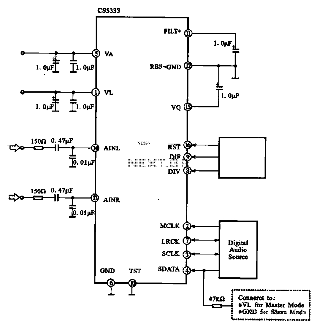
Audio A/D converter circuit configuration using the CS5333 chip, which is a high-performance 24-bit, 96 kHz stereo A/D converter commonly used in digital products. This circuit converts one or more audio signals into a digital signal for processing and...
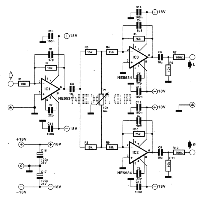
The circuit for spectator interference enables the implantation of mono sound at any point between stereo speakers. When potentiometer P1 is positioned at the midpoint of its range, it results in either the strengthening or weakening of the signal...
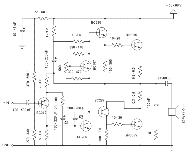
This is a simple and low cost 60W power amplifier. The optimal supply voltage is around 50V, but this amp can work from 30 to 60V. The maximum input voltage is around 0.8 - 1V. As you can see,...
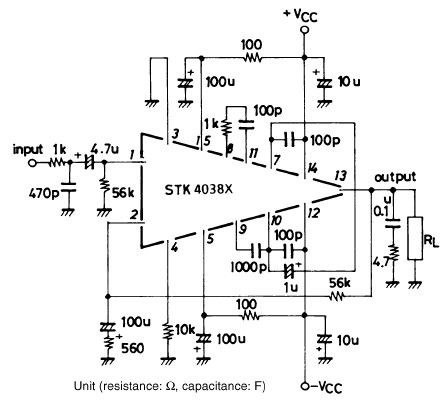
The STK4038-based 60-watt audio amplifier circuit project utilizes the STK4038X audio amplifier IC, designed to create a straightforward yet high-power and efficient audio power amplifier. Manufactured by Sanyo Corporation, this circuit delivers an output power of 60 watts with...