
SCA decoder

The circuit's core functionality hinges on the NE565 PLL, which operates by locking onto the frequency of the SCA subcarrier signal. This capability allows for effective demodulation of the signal, which is crucial in applications where subcarrier signals are utilized, such as in broadcasting or data transmission. The connection point between the FM discriminator and the de-emphasis network is critical, as it ensures that the SCA decoder receives a clean signal free from significant noise or distortion.
The tuning mechanism provided by the 5 kΩ potentiometer (R7) allows for some flexibility in adjusting the PLL to the desired frequency. The design's robustness is enhanced by the high-pass filter, which not only isolates the SCA signal from the main audio channel but also prevents lower frequency noise from affecting the demodulation process. The choice of capacitors (C1 and C2) and the resistor (R1) in the high-pass filter is essential for achieving the desired cutoff frequency, ensuring that the SCA signal is effectively coupled while attenuating unwanted components.
Following the PLL demodulation, the signal undergoes further processing through a three-stage de-emphasis network. This stage is designed to restore the frequency response of the SCA signal, particularly in the mid to high-frequency range, thus ensuring a clear and intelligible output. The output level of approximately 50 mV is suitable for subsequent stages, which may include additional amplification or further signal processing, depending on the specific application requirements.
Overall, this circuit design effectively utilizes the NE565 PLL for SCA signal recovery, with thoughtful consideration given to filtering and signal processing stages to ensure high fidelity and reliability in the demodulated output.The circuit uses a Signetics NE565 PLL (Phase-Locked Loop) as a detector to recover the SCA signal. The input to the SCA decoder circuit is connected to an FM receiver at a point between the FM discriminator and the de-emphasis filter network. The PLL, IC1, is tuned to 67 kHz by R7, a 5 potentiometer. Tuning need not be exact since the circuit will seek and lock onto the subcarrier. The demodulated signal from the FM receiver is fed to the input of the 565 through a high-pass filter consisting of two 510 pF capacitors (CI and C2) and a 4.7 resistor (Rl).
Its purpose is to serve as a coupling network and to attenuate some of the main channel spill. The demodulated SCA signal at pin 7 passes through a three-stage de-emphasis network as shown. The resulting signal is around 50 mV, with the response extending to around 7 kHz.
Related Circuits
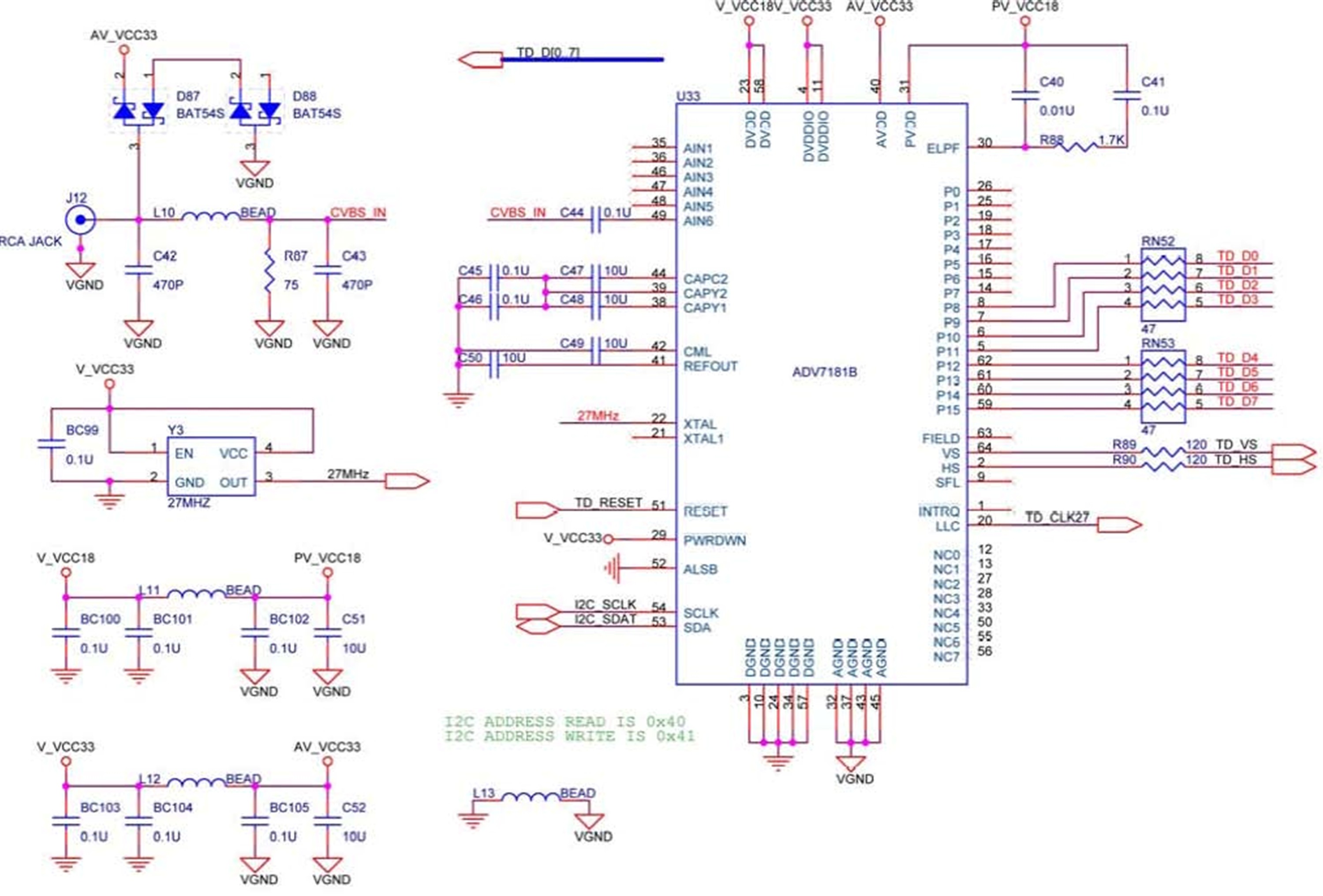
The DE2 board features an Analog Devices ADV7181 TV decoder chip. The ADV7181 is an integrated video decoder that automatically detects and converts standard analog baseband television signals (NTSC, PAL, and SECAM) into 4:2:2 component video data, which is...
This is a surround sound decoder. With this circuit, you can divide the 2-channel (right and left channel) stereo output into 4-channel output, which includes the right channel, left channel, center output, and rear output. This circuit will enhance...
The schematic diagram described here is a TMP01 Celsius Scale Temperature Sensor circuit. This circuit is used to convert the VPTAT output voltage. The TMP01 is a temperature sensor integrated circuit designed to provide an accurate temperature measurement in Celsius....
The TA2003PG and TA2003FG are integrated circuits designed for AM/FM radio applications. These ICs facilitate AM/FM radio functionality, including FM front-end and AM/FM intermediate frequency processing. When combined with the TA7368P mono power amplifier IC, a comprehensive AM/FM radio...
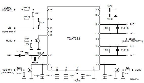
The pilot detector output is configured as an open collector output, requiring an external pull-up resistor. To set the decoder to "MONO," Pin 19 must be clamped to a voltage below 0.8V. The open collector output configuration allows for multiple...
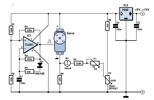
With some skill, an electronic scale can be constructed using a servo motor. Depending on the servo type, it can measure weights of up to approximately five kilograms (11 lbs) with reasonable accuracy. A detailed examination of the operating...