
TMP01 Celsius Scale Temperature Sensor

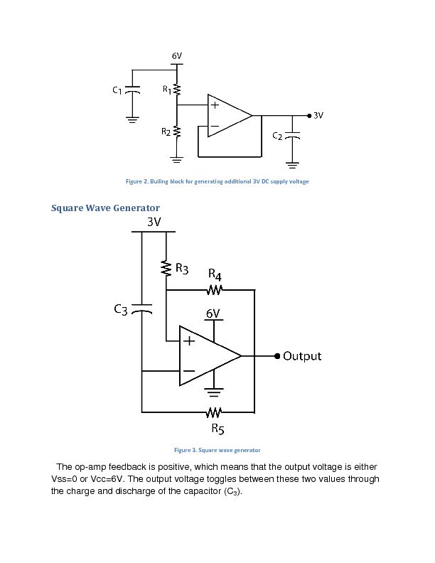
The TMP01 is a temperature sensor integrated circuit designed to provide an accurate temperature measurement in Celsius. It operates by generating a voltage output proportional to the temperature, utilizing the VPTAT (Voltage Proportional to Absolute Temperature) output voltage. This output can be interfaced directly with analog-to-digital converters (ADCs) or microcontrollers for further processing and display.
The schematic typically includes the TMP01 IC, which has pins for power supply, ground, and output voltage. It requires a stable power supply, often in the range of 4V to 30V, depending on the specific model. The output voltage from the TMP01 is linearly proportional to the temperature in degrees Celsius; for example, it outputs 10 mV per degree Celsius.
In practical applications, the circuit may include additional components such as resistors for pull-up or pull-down configurations, capacitors for noise filtering, and possibly an operational amplifier to enhance the output signal for better resolution. The sensor can be employed in various applications, including HVAC systems, environmental monitoring, and industrial automation, where precise temperature measurements are crucial.
The layout of the circuit should ensure minimal interference from external noise sources, and proper grounding techniques should be utilized to maintain signal integrity. Overall, the TMP01 Celsius Scale Temperature Sensor circuit is a reliable solution for real-time temperature monitoring and control in various electronic systems.The schematic diagram described here is a TMP01 Celsius Scale Temperature Sensor circuit. This circuit is used to convert the VPTAT output voltage that is . 🔗 External reference
Related Circuits
The report provides information related to light sensors, photoresistors, comparators, and associated circuits. It contains extensive details regarding detection. Light sensors are devices that detect and respond to light levels in the environment. A common type of light sensor is...

One-half of a 556 dual timer monitors the temperature of a liquid bath, controlling a heating element that maintains temperature within ±2°C over a 32° - 200°C range. The other half monitors the liquid level, disconnecting the heater when...
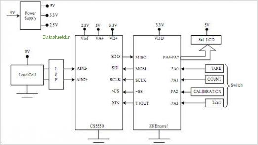
The diagram illustrates a block diagram for an agenda alarm and agenda thermometer system. It includes one temperature sensor, a real-time clock (RTC), a microcontroller (PIC), an EEPROM, a 7-segment display, and a keyboard. The EEPROM is utilized to...
The SP6691 circuit is designed to provide a high output voltage using a lower voltage boost regulator by incorporating a charge pump circuit. This configuration can convert a standard 30V boost regulator into a 60V boost regulator if necessary....
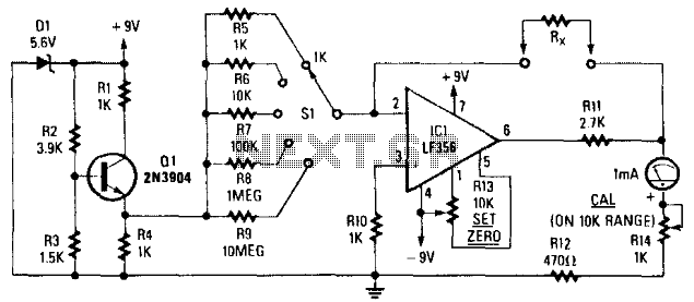
Rx is placed in the feedback path of IC1. A known reference current is chosen from the reference voltage generator Q1, D1, and resistors R5 through R9. A meter reading will be displayed, where R^ represents Rs through R9,...
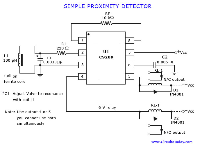
A simple proximity detector circuit diagram and schematic is presented, illustrating how to construct it using the proximity detector IC CS2009A, which is utilized for metal detector applications. The CS2009A is a versatile proximity sensor integrated circuit designed to detect the...