
Scanner Voice Squelch

The circuit is designed to enhance the listening experience by automatically muting the output during periods of silence or noise, which is particularly useful in environments where a scanner is used for communication. The operational amplifier plays a crucial role in amplifying the audio signal, ensuring that even faint speech is detected and processed effectively.
The rectifiers D1 and D2 are essential for converting the amplified audio signal into a suitable form for further processing. Switch Q1, controlled by the comparator U3, acts as a relay to mute the speaker when no valid audio signal is present. This function is vital to prevent listener fatigue caused by continuous noise or static.
The comparator U3 is configured to compare the amplified audio signal against a predefined threshold. When the audio signal exceeds this threshold, U3 activates switch Q1, allowing the audio to pass through to the speaker. Conversely, if the signal falls below the threshold, U3 will deactivate Q1, muting the speaker.
Transistor Q2 is used to complete the circuit path to ground, ensuring that the speaker is effectively muted when required. The audio amplifier U2 is responsible for driving the speaker with sufficient power, providing clear and audible sound output. The volume control resistor R3 allows for user adjustment of the audio level, enabling customization based on individual preferences or environmental conditions.
Finally, PL1 serves as a connection point for the scanner's speaker or headphone jack, allowing for versatile usage depending on the user's needs. Overall, this circuit effectively manages audio output from a scanner, enhancing the user experience by minimizing unwanted noise while ensuring clear communication when valid audio signals are present. This circuit detects the presence of audio (voice) on the output of a scanner. If the scanner stops on a "dead carrie r" or noise, the circuit mutes the speaker to avoid annoying noise. Ul amplifies speech and drives rectifier D1/D2 and switch Ql. Comparator U3 drives speaker switch Ql and indicator LED1. Q2 completes the speaker path to ground. U2 is an audio amplifier to drive the speaker. R3 is a volume control. PL1 connects to the scanner speaker or to the headphone jack.
Related Circuits
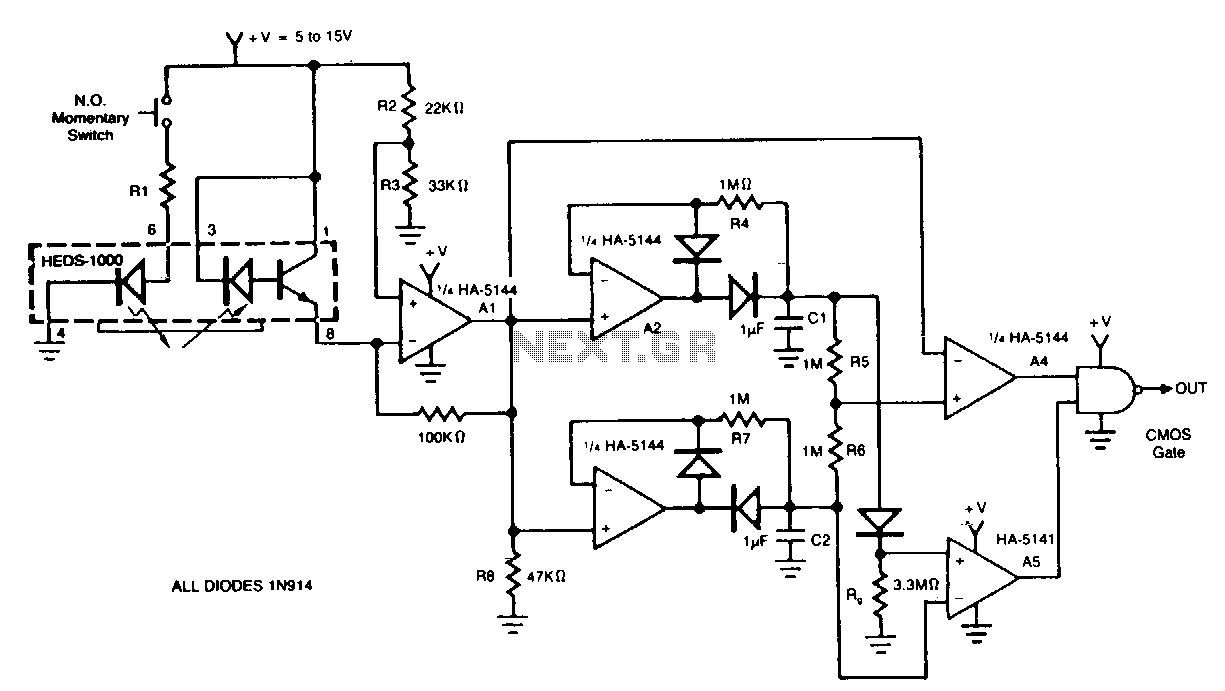
The circuit demonstrates a method for interfacing a HEDS-1000 emitter-detector pair with a HA-5144, intended for use as a barcode scanner circuit. The HA-5144 functions as an amplification system that transforms the widths of the printed barcode's bars and...
This circuit can be adjusted to operate within the frequency range of 87-108 MHz, achieving a transmission distance of approximately 20 to 30 meters. The design incorporates a pair of BC548 transistors, which, while not specifically designated as RF...
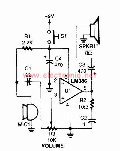
A voice amplifier can be designed using the LM386 power amplifier, which is intended for low voltage consumer applications. This simple circuit features variable gain and volume control. The gain is set internally to 20 to minimize the number...
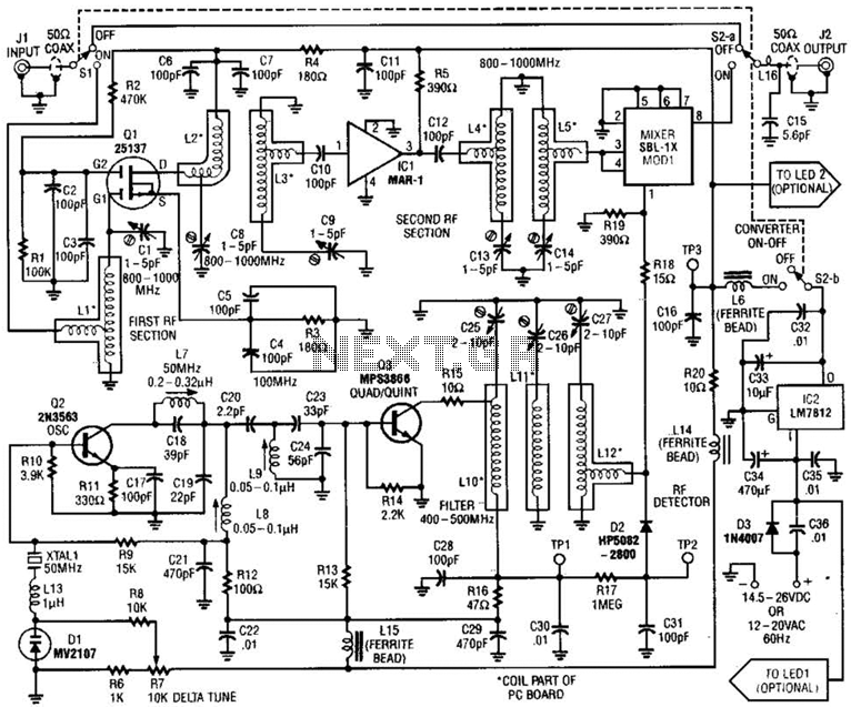
This converter allows the reception of frequencies ranging from 800 to 1000 MHz on any scanner that operates within the 400 to 500 MHz range. The converter can be configured to cover either the 800 to 900 MHz band...
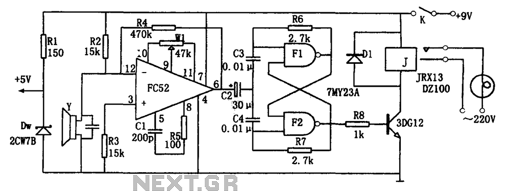
The voice-activated lamp circuit consists of an operational amplifier FC52, a flip-flop made from two NAND gates TMY23A, a relay J, a piezoelectric crystal speaker Y, and additional components. The flip-flop processes the sound signal from the speaker, converting...
Nowadays every institution needs automation. As a part of college automation, a project has been developed for a Voice Interactive System for College Automation. This project allows users to quickly access student attendance and marks through the telephone line...