2 Transistor FM Voice Transmitters

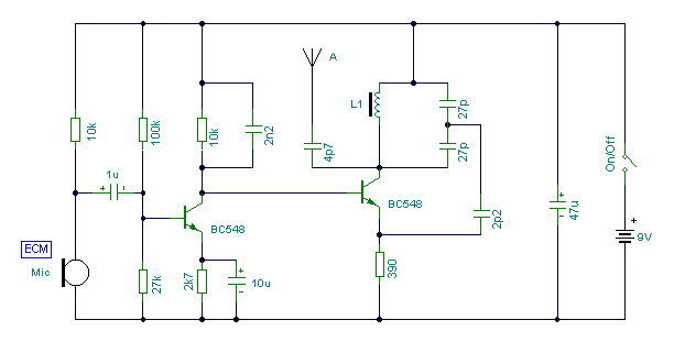
This circuit can be adjusted to operate within the frequency range of 87-108 MHz, achieving a transmission distance of approximately 20 to 30 meters. The design incorporates a pair of BC548 transistors, which, while not specifically designated as RF transistors, still yield satisfactory performance. An ECM microphone insert from Maplin Electronics, order code FS43W, is utilized; it is a two-terminal ECM, although standard dynamic microphone inserts can be employed by simply omitting the front 10k resistor. The inductor L1 is sourced from Maplin, part number UF68Y, consisting of 7 turns wound on a quarter-inch plastic former, complete with a tuning slug. This slug is adjustable to fine-tune the transmitter's frequency. The prototype achieved a tuning range from approximately 70 MHz to 120 MHz. The antenna is constructed from a few inches of wire; lengths exceeding 2 feet may dampen oscillations, preventing the circuit from functioning correctly. While RF circuits are ideally built on a printed circuit board (PCB), it is feasible to use veroboard, provided that all leads are kept short and tracks are appropriately broken at necessary points. It is important to avoid holding the circuit while speaking, as body capacitance acts as a 200 pF capacitor shunted to ground, which can dampen all oscillations. This issue has been observed in practical applications.
The circuit design utilizes BC548 transistors, which are general-purpose transistors commonly employed in low-frequency applications. In this RF circuit, they function adequately, demonstrating that non-specialized components can deliver reasonable results in certain contexts. The ECM microphone insert provides a means of audio input, converting sound waves into electrical signals. The choice of a two-terminal ECM microphone allows for a straightforward integration into the circuit, while the option to use a dynamic microphone by omitting the 10k resistor offers flexibility in component selection.
The inductor L1 plays a crucial role in determining the circuit's frequency characteristics. By adjusting the tuning slug, the inductance can be modified, thereby allowing the operator to fine-tune the transmitter's output frequency. This tuning capability is essential for ensuring compliance with the designated frequency range of 87-108 MHz. The prototype's ability to operate between 70 MHz and 120 MHz indicates a broad tuning range that can accommodate various applications.
The antenna design is critical for effective transmission. The recommendation for a short wire antenna, typically a few inches in length, is based on the need to maintain oscillation and signal integrity. Longer wire lengths can introduce unwanted capacitance and resistance, which can dampen the RF signals, leading to reduced transmission efficiency.
Construction techniques are also important in RF circuit design. Although PCBs are preferred for their reliability and performance, veroboard can be used effectively if care is taken to minimize lead lengths and ensure proper track management. This approach can help mitigate issues related to parasitic capacitance and inductance that often affect RF circuits.
Finally, the caution against holding the circuit while speaking highlights the importance of understanding body capacitance in RF applications. The presence of additional capacitance can significantly alter the circuit's performance, leading to unintended consequences such as signal distortion or loss of oscillation. Proper handling and circuit layout are essential for optimal operation.This circuit may be tuned to operate over the range 87-108MHz with a range of 20 or 30 metres. I have used a pair of BC548 transistors in this circuit. Although not strictly RF transistors, they still give good results. I have used an ECM Mic insert from Maplin Electronics, order code FS43W. It is a two terminal ECM, but ordinary dynamic mic inserts can also be used, simply omit the front 10k resistor. The coil L1 was again from Maplin, part no. UF68Y and consists of 7 turns on a quarter inch plastic former with a tuning slug. The tuning slug is adjusted to tune the transmitter. Actual range on my prototype tuned from 70MHz to around 120MHz. The aerial is a few inches of wire. Lengths of wire greater than 2 feet may damp oscillations and not allow the circuit to work. Although RF circuits are best constructed on a PCB, you can get away with veroboard, keep all leads short, and break tracks at appropriate points. One final point, don`t hold the circuit in your hand and try to speak. Body capacitance is equivalent to a 200pF capacitor shunted to earth, damping all oscillations. I have had some first hand experience of this problem. 🔗 External reference


