
Schematic Audio Power Amplifier with IC TDA2612 Schematic Diagram

The TDA2612 is a versatile audio power amplifier IC designed for driving speakers in various audio applications. It is capable of delivering a power output of 25 watts into a load of 4 ohms, making it suitable for medium-sized audio systems. The operational voltage range allows for flexibility in design, accommodating both lower and higher voltage power supplies, which is essential for different audio applications.
The frequency response of 20 Hz to 20 kHz indicates that the amplifier can reproduce the full range of audible sound, making it ideal for music and voice applications. The quiescent current of 70 mA suggests efficient operation, minimizing power consumption when the amplifier is idle.
In terms of design, the circuit typically includes essential components such as capacitors for filtering and stability, resistors for biasing, and possibly a heat sink to manage thermal performance during operation. The layout should ensure proper grounding and signal integrity to prevent interference and distortion in the audio output.
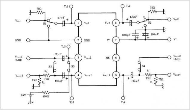
Overall, the TDA2612 amplifier circuit is a practical solution for creating high-quality audio amplification in various electronic projects, including home audio systems, portable speakers, and other sound reinforcement applications.This amplifier circuit based on IC TDA2612 produced by siemens, minimum voltage require for this circuit is 10 Volts and amximum voltage require 35 volts DC. Power output 25 watt with 4 ohm impedance. Frequncy response 20Hz to 20kHz. Quiescent current is 70 mA. This is a mono circuit amplifier. See circuit below : You are reading the Circuits of S chematic Audio Power Amplifier with IC TDA2612 And this circuit permalink url it is 🔗 External reference
Related Circuits
The interest in tube circuits remains significant. Therefore, I will provide a comprehensive circuit of a preamplifier that is sufficiently detailed. It is primarily composed of the main preamplifier department, the input selector department, application voltage delay, and the connection...
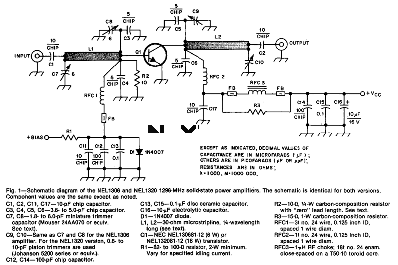
The design incorporates 30-ohm, 1/4 microstrip lines on the input and output. Capacitors C3, C4, C7, and C8, along with inductor L1, form a pi network that matches the low input impedance of the device to 50 ohms. Capacitors...
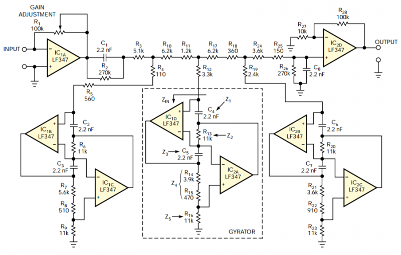
The filter should provide adjustable gain to maximize SNR at the audio processor's first stage. The filter's frequency response should also include a notch at 19 kHz to achieve maximum attenuation at the FM-subcarrier pilot-tone frequency and thus minimize...
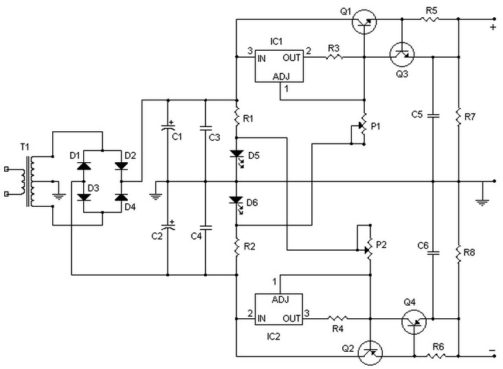
This circuit can deliver up to 15V per section (-15V and +15V), or up to 30V as a whole, for a maximum consumption of 2A. With modifications, it could be adjusted to provide up to 5A or more. Transistors...
NJM2274AR is a sub-package of NJM2274A. For a detailed description, please refer to NJM2274A. The datasheet for NJM2274AR can be downloaded from the link below. Manufactured by New Japan Radio Co., Ltd. The NJM2274AR is a component that serves as...
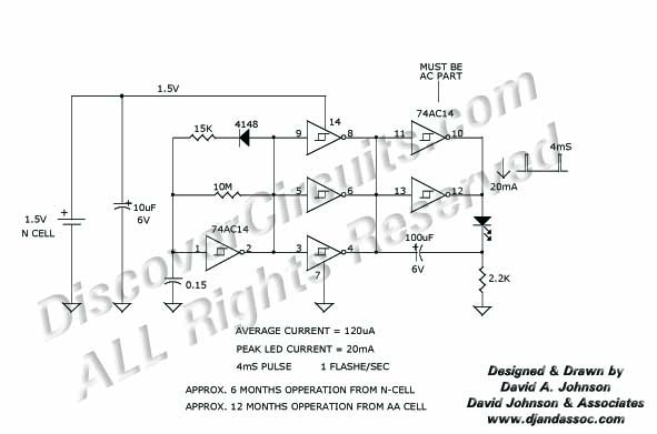
Many published circuits that flash LEDs require 3 volts or more. This circuit utilizes a single inexpensive C-MOS IC and can flash an LED for an entire year on a single 1.5-volt AA alkaline battery cell. The circuit employs...