
schematic computer arithmetic organ

A schematic diagram serves as a vital tool in the design and analysis of electronic circuits. It provides a visual representation of the electrical connections and functions of various components, allowing engineers and technicians to understand the layout and operation of the circuit easily. The use of standardized symbols for components such as resistors, capacitors, and vacuum tubes ensures clarity and uniformity across different schematics.
In the context of CSIRAC, a pioneering computer developed in the 1940s, the schematic diagram would depict the arrangement and interconnections of its key components. Vacuum tubes functioned as the primary switching elements, facilitating the processing of binary data. Capacitors were employed for filtering and timing applications, while resistors were used to control current flow and voltage levels within the circuit.
The schematic diagram not only aids in the assembly of the circuit but also serves as a reference for troubleshooting and maintenance. By analyzing the diagram, technicians can identify potential issues, such as faulty components or incorrect connections, and implement corrective measures efficiently. Overall, schematic diagrams are an essential part of the electronic engineering process, providing a clear and concise means of documenting and communicating circuit designs.A schematic diagram shows the detailed connections between all the components in a circuit. Such diagrams were used to build circuits and later for testing. For CSIRAC, the most common components were vacuum tubes (valves), capacitors and resistors. Schematic diagrams are also known as circuit diagrams. 🔗 External reference
Related Circuits
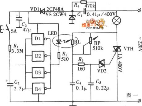
The diagram illustrates a lamp dimmer that gradually increases and decreases light intensity. This feature prevents sudden illumination, which can be a shock to the human eye, and also minimizes damage caused by inrush current when the lamp is...
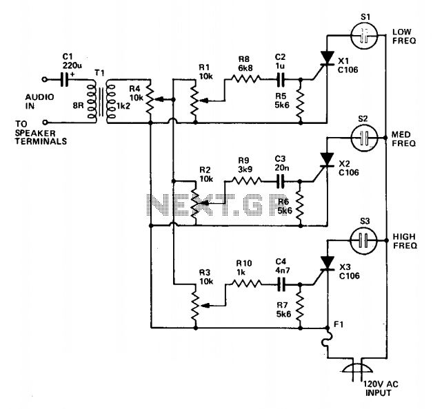
Three lights are controlled by three channels. One light pulses in response to the bass, another illuminates with mid-range sounds, and the last lights up for high notes. Four level controls allow adjustment of the overall light level and...
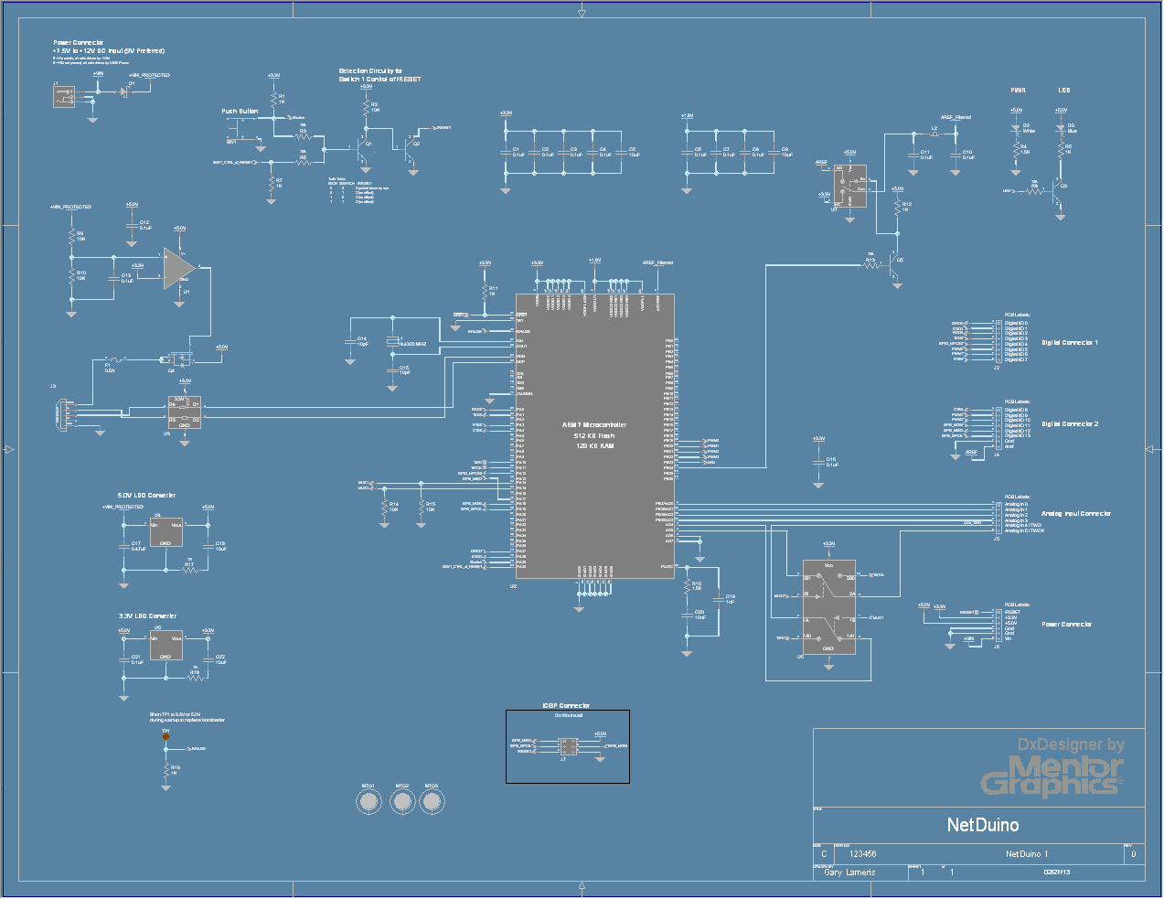
Posts from PCB Schematic Design with DxDesigner tagged DxDesigner. The information pertains to the use of DxDesigner, a tool utilized for PCB schematic design. DxDesigner is part of the broader suite of design tools that facilitate the creation, editing, and...
This circuit employs an 87C57 microcontroller along with several peripherals to convert X-10 power-line carrier-code formats from a personal computer for use with an X-10 power-line interface in a home-control system. Software details can be found in the reference. The...

The Heater Fan Controller is designed around the PIC12F675 microcontroller. It reads a 10k linear potentiometer and generates appropriately timed pulses to control the DC motor that operates the fan. The lowest setting completely cuts off the power. This...
The circuit monitors PC keyboard activity through a five-pin DIN connector J1. When a key is pressed, the keyboard transmits a series of negative-going pulses on pin 2. In conjunction with Q1 and C3, the operational amplifier operates as...