
LED Lamp Dimmer Circuit Schematic Diagram

The lamp dimmer circuit is designed to provide a smooth transition in lighting, which is particularly beneficial in environments where abrupt changes in brightness could cause discomfort or visual strain. The core component of the circuit is the optocoupler, which serves to isolate the control signal from the high-voltage side of the circuit, ensuring safety and reliability.
The six inverter circuits are arranged to form a robust driver that can handle varying loads efficiently. The use of four inverters in parallel enhances the circuit's ability to drive higher currents, making it suitable for a range of LED lamp applications. This configuration allows for better thermal management and reduces the risk of overheating, which is critical in maintaining the longevity of LED components.
In operation, the dimmer circuit adjusts the duty cycle of the output signal, effectively controlling the power delivered to the LED lamp. By varying the time the LEDs are turned on and off, the perceived brightness can be modulated smoothly. This method is particularly effective for LED lamps, as it allows for energy savings and extends the lifespan of the lighting system.
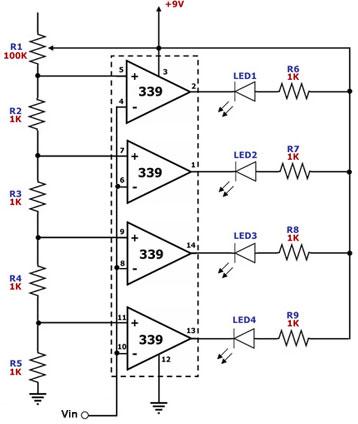
Overall, this lamp dimmer circuit not only improves user comfort by providing adjustable lighting but also enhances the performance and durability of LED lamps through its innovative design.The diagram is lamp dimmer which has the function of light gradually, gradually eliminate. It does not appear the light stimulation of the human eye when the lights suddenly illuminated, and also can reduce the damage when open lamp impact current to the bulb, circuit is shown in the diagram. This circuit is LED driver circuit in optocoupler whic h consists of a six inverter circuit, in order to add the driver ability of the circuit, four inverters are use in parallel. You are reading the Circuits of LED Lamp Dimmer Circuit And this circuit permalink url it is 🔗 External reference
Related Circuits
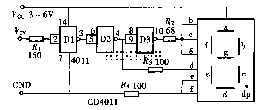
The door circuit logic pen text display can take many forms, utilizing various logic gates such as inverters, NAND gates, NOR gates, and others. A logical pen, exemplified by the NAND gate CD4011, can be used in conjunction with...
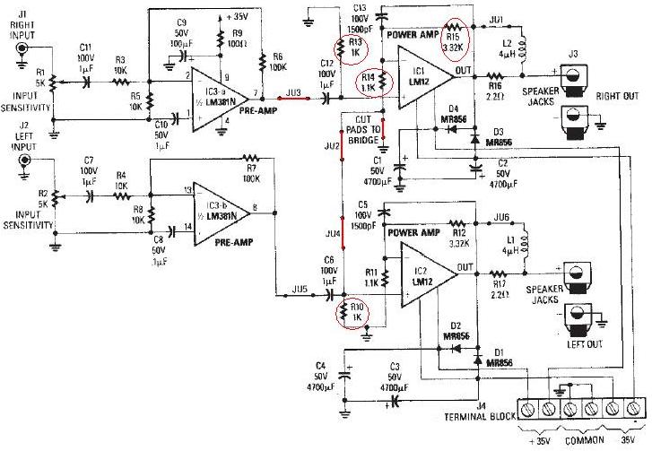
The LM12 audio amplifier circuit is designed to deliver high output power for 8 ohm or 4 ohm load impedances. The maximum output power provided by the LM12 audio amplifier is approximately 60 watts for a 4 ohm load...

The circuit consists of eight cascaded identical cells, each cell being a DC-controlled active phase shifter. Since the DC control is common for all shifters, the circuit is adjusted by tuning resistor RA so that the phase difference between...
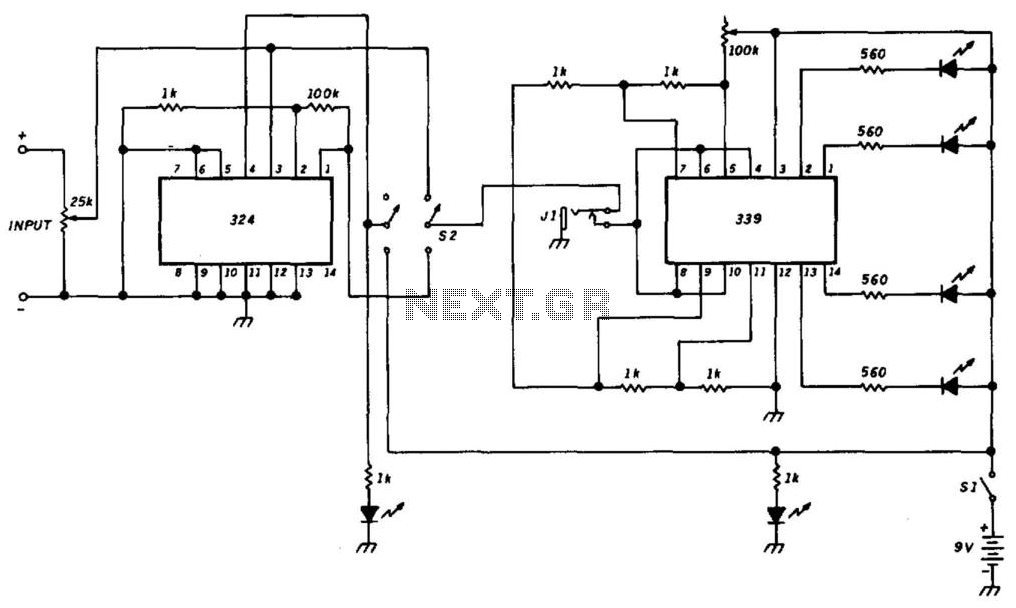
This circuit utilizes a DC amplifier (LM324) in a bar-graph configuration that employs an LM339 quad comparator integrated circuit (IC) to detect DC levels. The LEDs illuminate for every 100 mV increase. The LM324 operational amplifier is set up...
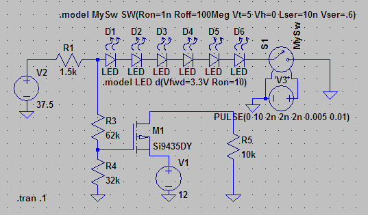
A suitable method to sense when some LEDs in a garage door opener are illuminated. A power source, potentially the same as Vout, connects to a 1.5 kΩ resistor, which then connects to six LEDs followed by a transistor....
This circuit is designed as a simple LED bar graph voltmeter. Each operational amplifier in the LM339 quad package functions as a comparator, comparing the input voltage (Vin) to a series of fixed voltage levels that are proportional to...