
Schematic Diagram circuit andexplanation

The power inverter circuit is designed to convert a DC input voltage to a stable square wave AC output. The circuit operates at a frequency typically set to 60 Hz, which aligns with standard electrical systems in many regions. The frequency is adjustable via a potentiometer, allowing for flexibility in application.
The circuit's output can be interfaced with various transformers. Off-the-shelf transformers are readily available and can be utilized effectively. However, for specialized applications requiring specific voltage or current characteristics, custom-wound transformers may provide enhanced performance, ensuring that the inverter meets the precise requirements of the load.
To facilitate higher power outputs, the design allows for the paralleling of additional MOSFETs. This capability is crucial in applications where increased current handling is necessary. Each MOSFET in the circuit should be equipped with appropriate heat sinks, particularly the RFP50N06 MOSFETs, which have specifications of 50 amps and 60 volts. Proper thermal management is essential to maintain the reliability and efficiency of the circuit.
Safety considerations are paramount in the design. A fuse rated for 32 volts and approximately 10 amps per 100 watts of output should be incorporated into the power line. This fuse serves as a protective measure to prevent overcurrent situations that could lead to circuit damage or fire hazards. Furthermore, it is critical to ensure that the power leads are constructed from sufficiently thick wire to handle the high current draw without excessive voltage drop or overheating.
While the circuit can be scaled for various power levels, there are practical limitations. For instance, the request for a 1000-watt inverter presents significant challenges. Operating from a 12-volt source in such a scenario would result in an input current nearing 100 amps, which necessitates the use of very large gauge wire to safely accommodate the high current. This requirement underscores the importance of careful consideration in the design and implementation of high-power inverter systems.This power inverter circuit will provide a very stable Square Wave Output Voltage. Frequency of operation is determined by a pot and is normally set to 60 Hz. Various off the shelf transformers can be used. Or Custom wind your own for best results. Additional MosFets can be paralleled for higher power. It is recommended to Have a Fuse in the Power Line and to always have a Load connected , while power is being applied. The Fuse should be rated at 32 volts and should be aproximately 10 Amps per 100 watts of output. The Power leads must be heavy enough wire to handle this High Current Draw! appropriate Heat Sinks Should be used on the RFP50N06 Fets. These Fets are rated at 50 Amps and 60 Volts. Other types of Mosfets can be substituted if you wish. There ARE Limitations! I have had numerous requests for an Inverter for 1000 watts and Even MORE. Sorry I Don`t feel this is Practical. At 1000 Watts and operating from a 12 Volt Source, the Input Current will be close to 100 AMPS. That would Require a HUGH Size of a Primary Wire. 🔗 External reference
Related Circuits
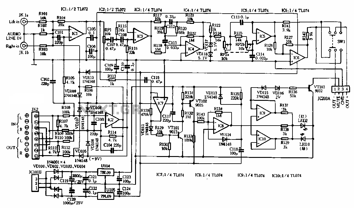
The schematic illustrates the subwoofer amplifier stage, specifically the pre-amplifier circuit and the signal processing circuit. Notably, it features two LM3886 power ICs from the American company NS, which facilitate BTL (Bridge-Tied Load) speaker operation at an 8-ohm impedance...
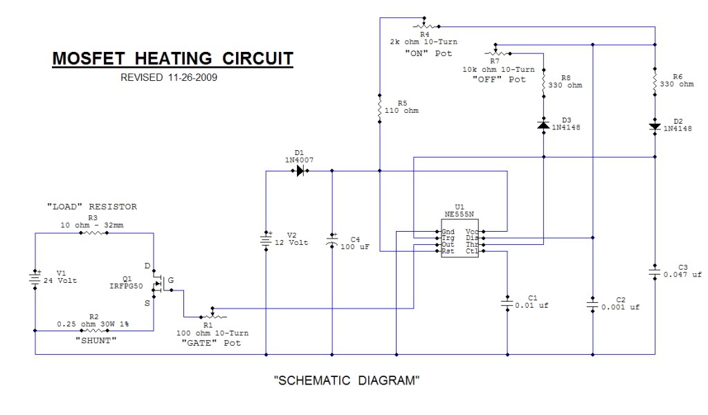
This open-source thread focuses on the development of a "MOSFET Heating Circuit," which is a modified version of an existing design. The MOSFET Heating Circuit is designed to efficiently manage and control heating elements using MOSFET technology. MOSFETs (Metal-Oxide-Semiconductor Field-Effect...
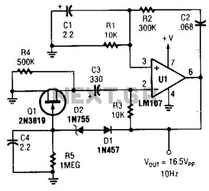
This Wien-bridge sine-wave oscillator utilizes a 2N3819 as an amplitude stabilizer. The 2N3819 functions as a variable-resistance element within the Wien bridge. The Wien-bridge oscillator is a type of electronic oscillator that generates sine waves. It employs a bridge circuit...
By adjusting the oscillators so their frequencies are very nearly the same, the difference between them is made audible as a beat note. This beat note changes slightly when the search loop is moved over or near to a...
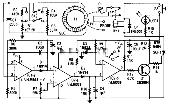
This circuit is an adjustable electronic circuit breaker that features a toroidal transformer designed to sense a 60-Hz load current. The transformer, labeled as T1, has a two-turn winding for the primary side and 100 turns of #30 gauge...
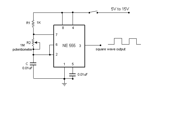
This is a very simple circuit utilizing a 555 timer IC to generate a square wave of frequency that can be adjusted by a potentiometer. With values given, the frequency can be adjusted from a few Hz to several...