
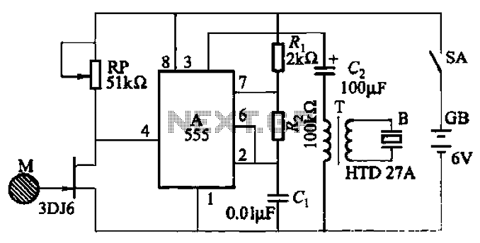
Variable Square wave oscilator with 555 circuit

In order to ensure a 50% (approx.) duty ratio, R1 should be very small when compared to R2. However, R1 should be no smaller than 1kΩ. A good choice would be R1 in kilohms and R2 in megaohms. One can then select C to fix the range of frequencies.
The circuit employs the 555 timer in astable mode, where it continuously oscillates between high and low states, producing a square wave output. The frequency of oscillation is determined by the resistances R1 and R2 and the capacitance C, as per the provided formula. The 555 timer's output can be connected to various loads, such as LEDs or speakers, depending on the desired application.
To construct the circuit, connect the 555 timer's pins as follows: Pin 1 (GND) to ground, Pin 8 (VCC) to a suitable power supply (typically between 4.5V and 15V), Pin 2 (TRIG) and Pin 6 (THRESH) are connected together, and Pin 3 (OUT) will provide the output square wave. The resistors R1 and R2 are connected in series between VCC and Pin 6, with Pin 6 also connected to the capacitor C, which is then connected to ground.
The choice of R1 and R2 is critical for achieving the desired frequency range. As noted, R1 should be kept relatively small compared to R2 to maintain a duty cycle close to 50%. A potentiometer can be used for R2 to allow for easy adjustment of the frequency. The capacitor C can be varied to extend the frequency range further down into the lower frequency spectrum, depending on the application requirements.
Overall, this circuit is versatile and can be adapted for various uses, such as tone generation, timing applications, or as a clock pulse for digital circuits. Proper selection of components and configurations will ensure reliable operation across the desired frequency range.This is a very simple circuit utilising a 555 timer IC to generate square wave of frequency that can be adjusted by a potentiometer. With values given the frequency can be adjusted from a few Hz to several Khz. To get very low frequencies replace the 0.01uF capacitor with a higher value. The formula to calculate the frequency is given by: 1/f = 0.69 * C * ( R1 + 2*R2). The duty cycle is given by: % duty cycle = 100*(R1+R2)/(R1+ 2*R2). In order to ensure a 50% (approx.) duty ratio, R1 should be very small when compared to R2. But R1 should be no smaller than 1K. A good choice would be, R1 in kilohms and R2 in megaohms. You can then select C to fix the range of frequencies. 🔗 External reference
Related Circuits
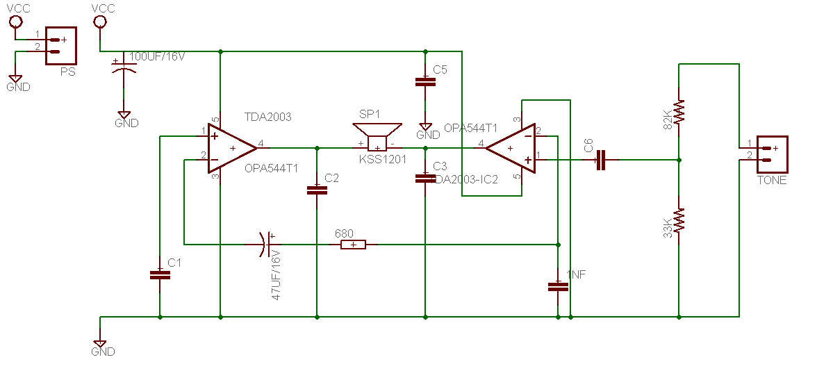
This is a design for a tone control circuit. The circuit features the LM1036, which is a DC-controlled tone (bass/treble), volume, and balance circuit suitable for stereo applications in car radios, televisions, and audio systems. The LM1036 integrated circuit is...
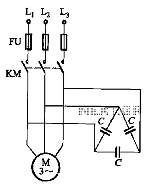
Asynchronous motor reactive power compensation involves directly connecting a capacitor to the stator windings of the asynchronous motor to enhance its power factor. This method is particularly effective for synchronous motors, as it reduces energy consumption related to reactive...
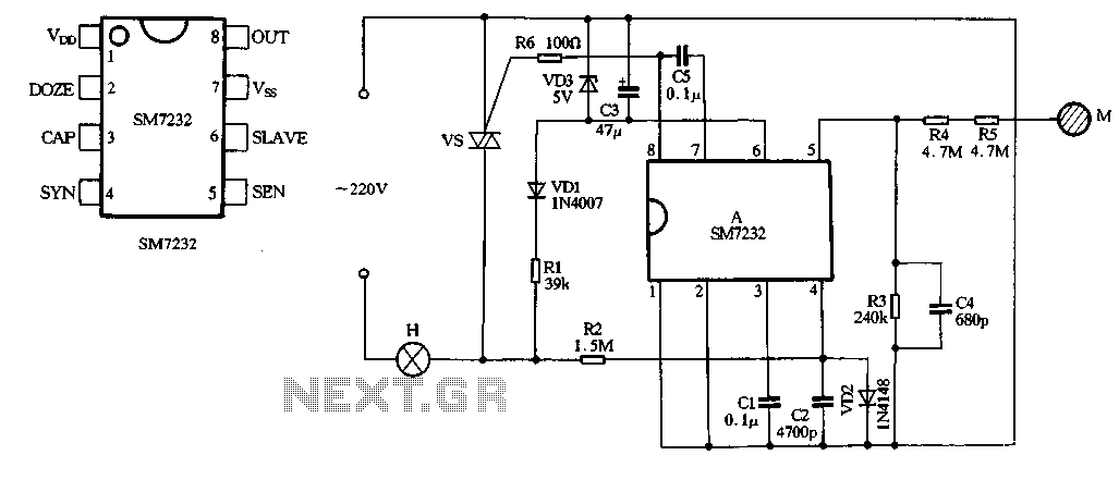
The core component of the circuit is the dimmer, utilizing the SM7232 integrated circuit. The pin configuration includes: 1) VDD, the positive power supply terminal; 2) DOZE; 3) CAP; 4) SYN, which synchronizes input power frequency using an internal...
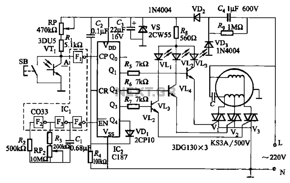
The circuit depicted in Figure 3-5 can be controlled manually using button SB or automatically via light detection using phototransistor VTj. When light from a flashlight is detected by phototransistor VTj, the fan will activate, adjusting its speed automatically...
The circuit utilizes a 555 integrated circuit (IC) configured as a non-stable multivibrator. When a sensor detects proximity to a high-voltage electrified body, a piezoelectric ceramic sheet generates an alarm. Additionally, when in proximity to a high-frequency electric field,...
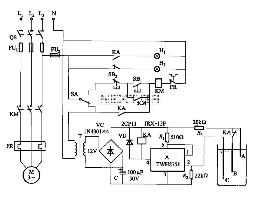
The power switch integrated circuit A features a straightforward design with high sensitivity, ensuring reliable operation. It is part of an automatic liquid level control circuit. When the water level at electrode B drops below 2 feet (0V), circuit...