
Schematic Diagram of Dashboard Digital Voltmeter
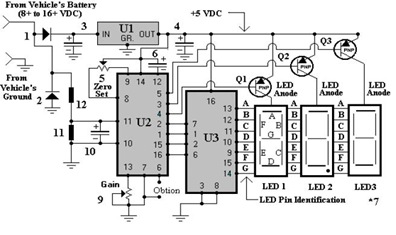
The dashboard digital voltmeter circuit is designed to provide an accurate measurement of voltage levels and display them on a digital interface. The primary components of the circuit typically include a microcontroller, an analog-to-digital converter (ADC), a display module (such as a 7-segment display or an LCD), resistors, capacitors, and a voltage reference.
The microcontroller serves as the central processing unit, interpreting the voltage readings from the ADC and controlling the display output. The ADC converts the analog voltage signal into a digital format that the microcontroller can process. It is crucial to select an ADC with sufficient resolution to ensure accurate voltage readings.
The display module is responsible for visually presenting the measured voltage. Depending on the complexity of the design, the display can be configured to show additional information such as battery status or voltage range. The choice of display technology (LED, LCD, etc.) will depend on the desired visibility and power consumption requirements.
The PCB layout is essential for ensuring that the components are arranged efficiently and that signal integrity is maintained. Proper placement of components can minimize noise and interference, which is particularly important in sensitive measurement applications. The PCB should also include appropriate traces for power distribution and signal routing.
In addition to the schematic diagram, a comprehensive parts list should be provided, detailing each component's specifications, such as resistance values, capacitance, and power ratings. This list aids in sourcing components and ensures compatibility within the circuit.
Overall, the design of a dashboard digital voltmeter circuit requires careful consideration of component selection, layout design, and functionality to achieve a reliable and accurate measurement tool.If you want to to try to make a Dashboard Digital Voltmeter Circuit Diagram including part lists, the PCB building and the placement of the components, you may download the article in full pdf here 🔗 External reference
Related Circuits
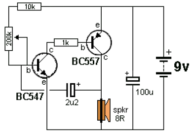
The ticking bomb sound generator circuit diagram operates by charging a 2.2 µF capacitor. When the voltage at the base of the NPN transistor reaches 0.65 V, it activates the transistor, which in turn activates the BC557 transistor, increasing...
This ion detector circuit is designed to sense static charges and free ions present in the air. It is capable of detecting the presence of free ions, static electricity, or high voltage leakage. The project utilizes a short whip...
The metal detector circuit consists of several key components including the probe oscillator, reference oscillator, oscillation signal processor, mixing amplifier, and ammeter PA. The probe oscillator is made up of the oscillating tube VI, exploration coil L1, capacitors C1...
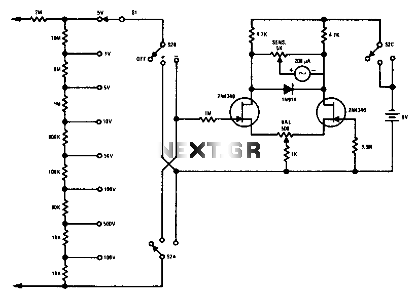
This FETVM replaces the function of the VTVM while eliminating the need for a traditional line cord. Additionally, it offers significantly improved drift rates compared to vacuum tube circuits, enabling a 0-volt full-scale range that is generally impractical with...
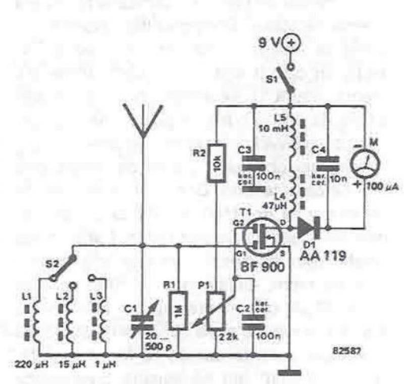
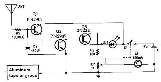
An RF field detector circuit suitable for measuring and verifying the power of antennas and transmitters can be constructed using transistors and common electronic components. This circuit employs a radio frequency transistor, specifically a MOS-FET with two gates. The...
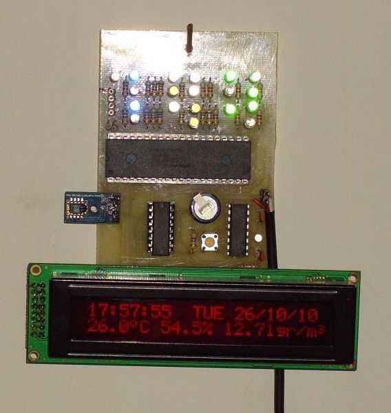
I use a RealTimeClock Maxim DS1305. The RTC backup power is a supercapacitor (0.22F). I test it for 4 weeks, works fine. For this reason it doesn't have the capability to change the time, but you can do small...
Warning: include(partials/cookie-banner.php): Failed to open stream: Permission denied in /var/www/html/nextgr/view-circuit.php on line 713
Warning: include(): Failed opening 'partials/cookie-banner.php' for inclusion (include_path='.:/usr/share/php') in /var/www/html/nextgr/view-circuit.php on line 713