
RF field detector circuit diagram

The RF field detector circuit is designed to provide accurate measurements of radio frequency fields in various frequency ranges, making it essential for testing and validating the performance of antennas and transmitters. The use of a MOS-FET transistor allows for high sensitivity and low noise operation, which is crucial for detecting weak RF signals.
The circuit's gain factor, controlled by potentiometer P1, enables the user to adjust the sensitivity according to the strength of the incoming RF signal. This flexibility is important for applications where signal strength may vary significantly, ensuring that the circuit can effectively measure both weak and strong signals without distortion.
The inclusion of switch S2 facilitates the selection of three distinct frequency ranges, allowing the user to optimize the circuit's performance for specific applications. Each range is designed to cover a specific band of frequencies, ensuring that the detector can accurately measure signals within those limits. The first range (L1) covers low frequencies from 480 kHz to 2.4 MHz, suitable for VHF applications. The second range (L2) extends from 2.4 MHz to 12 MHz, which encompasses many amateur radio bands. The third range (L3) provides coverage from 12 MHz to 40 MHz, accommodating higher frequency transmissions.
The use of a telescopic antenna with a length of 30 cm enhances the circuit's capability to receive RF signals effectively. This type of antenna is advantageous due to its portability and ease of adjustment, allowing for better alignment with the direction of incoming signals.
Overall, the RF field detector circuit is a versatile tool for engineers and technicians involved in RF applications, providing essential functionality for the measurement and verification of antenna and transmitter performance across a range of frequencies.An RF field detector circuit that can be used in measurement and verification stage power antennas and transmitters can be designed using some transistors and common electronic components. This RF field detector circuit is designed with a radio frequency transistor type MOS-FET with two gates.
Gain factor is set by the potentiometer P1. S2 switch allows selecting one of three ranges: 480 kHz ... 2.4 MHz (L1), 2.4 ... 12 MHz (L2) and 12 ... 40 MHz (L3). A telescopic antenna with a length of 30 cm is sufficient for the antenna. 🔗 External reference
Related Circuits
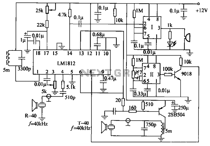
The ultrasonic anti-collision circuit is designed using the LM1812 integrated circuit, which controls both the transmission and reception functions. A distance control potentiometer allows for adjustments within a range of 2 to 3 meters. The timebase circuit is constructed...
A modification to David Knight's linear detector circuit was developed to create a high-fidelity AM receiver requiring an ultra-linear AM detector. The revised circuit eliminates the meter circuit and many bypass capacitors, resulting in a design with a finite...
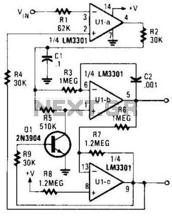
The Phase-Locked Loop (PLL) will synchronize with an input signal, providing both triangle and square wave outputs. A quad operational amplifier can be utilized in this circuit, making it suitable for audio and low-frequency radio applications. The Phase-Locked Loop (PLL)...
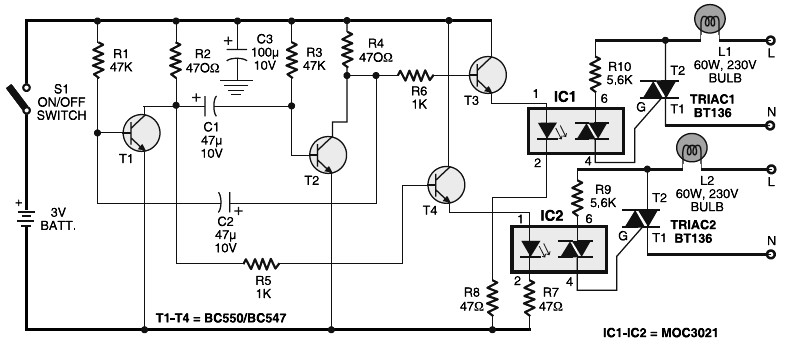
Portable 230V lamp flasher circuit diagram. The circuit is entirely transistorized and powered by a battery. A free-running oscillator circuit is implemented using two low-power, low-noise transistors, T1 and T2. One of these transistors remains in a conducting state...

This circuit is designed for a UHF TV antenna and provides a 15 dB preamplification. It is constructed using a transistor and minimal components. The schematic features the BF180 UHF transistor. The first stage consists of a band-pass filter...
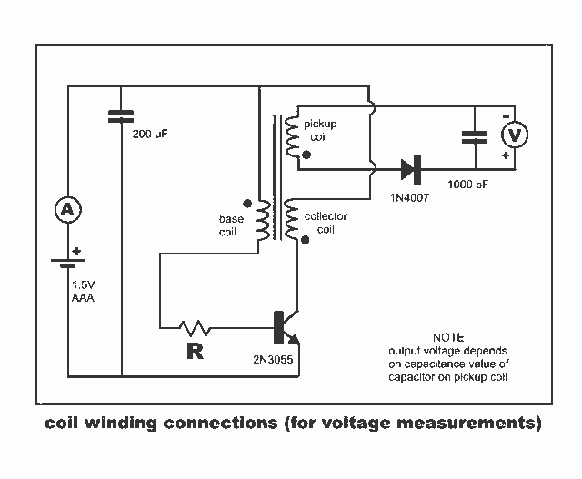
New Jewel Thief "Resonate LCR Circuit" with significantly reduced energy consumption. Measurements of voltage and current for the Joule thief. The Jewel Thief circuit, particularly the "Resonate LCR Circuit," is an innovative low-power design that enhances energy efficiency while maintaining...