
Schmitt Trigger Photo switch

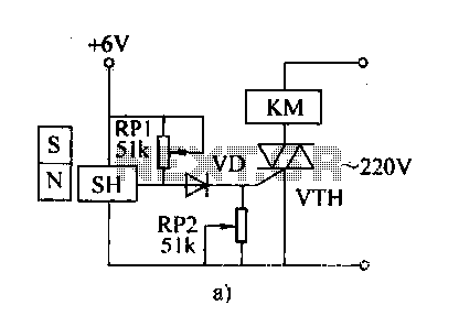
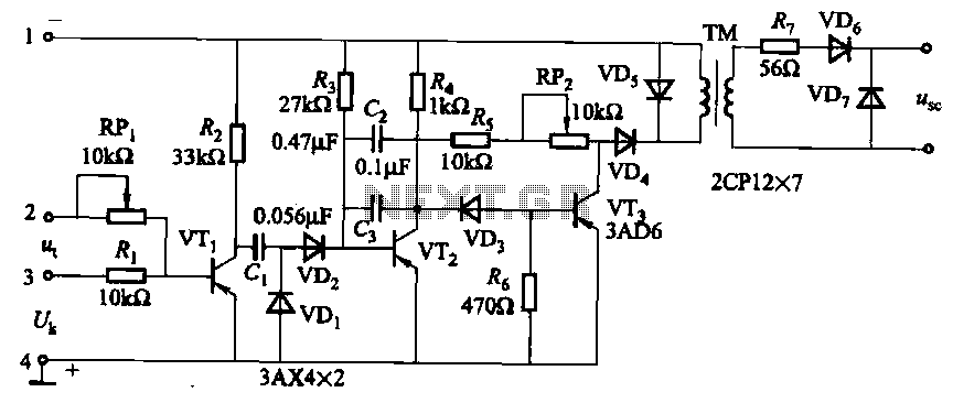
The described circuit functions as a Schmitt Trigger, utilizing a cadmium sulfide photo cell as the primary sensor to detect ambient light levels. The circuit is designed to control a relay, which in turn can switch a street lamp on and off based on the light conditions, specifically at dawn and dusk. The relay selected for this application has a coil resistance of 120 ohms and operates at 12 volts, making it suitable for controlling typical street lighting systems.
The photo cell is strategically shielded from direct light emitted by the lamp to avoid erroneous triggering. It is typically mounted above the lamp on a reflector, oriented upward to receive ambient light while minimizing the influence of the lamp's own illumination.
In terms of circuit configuration, the photo cell is connected in series with a potentiometer, allowing for fine-tuning of the voltage at their junction, which is fed to the base of the first PNP transistor (Q1). This arrangement enables adjustment of the circuit's sensitivity to ambient light, effectively setting the threshold at which the relay activates or deactivates.
The two PNP transistors are configured with a common emitter resistor to facilitate positive feedback. This feedback mechanism ensures that when one transistor turns on, the other turns off, thereby creating a hysteresis effect that stabilizes the switching action. Under low-light conditions, the resistance of the photo cell increases, resulting in a higher voltage at the base of Q1 compared to Q2. This causes Q2 to turn on and activate the relay, thus switching the lamp on.
The circuit exhibits specific switching thresholds, approximately 8 volts and 4 volts, determined by the resistor values in the circuit. Adjustments to the resistor, such as replacing the 7.5K resistor with a lower value like 3.3K, can narrow the switching range to approximately 3.5 volts and 5.5 volts, allowing for more precise control over the relay's operation. The potentiometer must be recalibrated to maintain the desired voltage level at the ambient light threshold, typically around 4.5 volts.
Overall, this Schmitt Trigger circuit provides a reliable solution for automatic street lighting control, utilizing simple electronic components to achieve effective light level detection and relay activation.This is basically a Schmitt Trigger circuit which receives input from a cadmium sulfide photo cell and controls a relay that can be used to switch off and on a street lamp at dawn and dusk. I have built the circuit with a 120 ohm/12 volt relay and monitored performance using a lamp dimmer, but did not connect the relay to an outside light.
The photo cell should be shielded from the lamp to prevent feedback and is usually mounted above the light on top of a reflector and pointed upward at the sky so the lamp light does not strike the photo cell and switch off the lamp. The photo cell is wired in series with a potentiometer so the voltage at the junction (and base of transistor) can be adjusted to about half the supply, at the desired ambient light level. The two PNP transistors are connected with a common emitter resistor for positive feedback so as one transistor turns on, the other will turn off, and visa versa.
Under dark conditions, the photo cell resistance will be higher than the potentiometer producing a voltage at Q1 that is higher than the base voltage at Q2 which causes Q2 to conduct and activate the relay. The switching points are about 8 volts and 4 volts using the resistor values shown but could be brought closer together by using a lower value for the 7.5K resistor.
3.3K would move the levels to about 3.5 and 5.5 for a range of 2 volts instead of 4 so the relay turns on and off closer to the same ambient light level. The potentiometer would need to be readjusted so that the voltage is around 4.5 at the desired ambient condition.
🔗 External reference
Related Circuits
The automatic weapon features a magnetic switch circuit that is simple, reliable, has a low failure rate, and offers good versatility. It can be used for output performance or converted into mechanical displacement applications. The circuit diagram utilizes a...
The project presented is a universal QRP T/R (transmit/receive) switch designed to connect any QRP (less than 10W) receiver and CW (continuous wave) transmitter seamlessly. The design focuses on essential functionalities, making it suitable for simple transmitters and receivers...
This photocell is best mounted at tie level between the rails. The variable resistor adjusts the sensitivity of the circuit. This circuit can be powered by either 6 or 12 volts - BE SURE to use the proper relay;...
This project involves a simple touch switch circuit that can also be utilized to activate a relay instead of an LED and resistor. The circuit exhibits high sensitivity due to the use of two transistors configured as a Darlington...
The circuit is designed for inductive loads, specifically within a thyristor power unit, such as a three-phase step-down DC motor speed control and other applications. It is capable of delivering sufficient output power to trigger a thyristor rated at...
Ultrasonic Switch. A circuit of a new type of remote control switch is described here. This circuit operates with inaudible sound waves. The ultrasonic switch operates by utilizing ultrasonic frequencies, which are sound waves above the range of human hearing...