
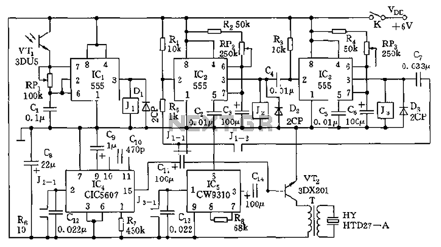
Resistive-Capacitive sinusoidal synchronous reset control transistor trigger circuit

This circuit is particularly beneficial for controlling the speed of DC motors, where precise regulation of power is essential. The thyristor acts as a switch that can handle high current loads, making it suitable for industrial applications. The ability to adjust the pulse width via the potentiometer RPz provides flexibility in controlling the motor's speed, enabling fine-tuning of performance based on the specific requirements of the load.
The circuit typically includes a phase control mechanism that adjusts the timing of the thyristor's conduction phase, which in turn modifies the average voltage and current supplied to the motor. This phase control is achieved through a phase shift circuit that can vary the triggering point of the thyristor within a 180-degree range, allowing for smooth acceleration and deceleration of the motor.
In practical applications, additional components such as diodes for flyback protection, capacitors for smoothing the output, and resistors for current limiting may be incorporated to enhance reliability and performance. The overall design must ensure that the circuit can withstand the thermal and electrical stresses associated with high power levels, necessitating careful selection of components and thermal management strategies.
This circuit configuration is widely utilized in various industrial settings, including conveyor systems, fans, and pumps, where precise motor control is critical for operational efficiency.The circuit is suitable for inductive loads in general thyristor power unit (three-phase step-down DC motor speed and other exceptions), the output power more than enough to trigger thyristor 100A. Adjustment potentiometer RPz, can change the output pulse width. Phase shift range of about 180.
Related Circuits
The F84 MRTC was my second design of a miniature real-time controller. This version uses PIC16F84 running with a low power X-tal 32,768Hz. The scheduler for 6-channel output was saved in EEPROM. No terminal for serial downloading of the...
The circuit consists of four light-controlled electronic switches, timing circuits, voice circuits, audio circuits, and other components. It is designed to celebrate birthdays or similar occasions, with features such as birthday candles that can be lit or extinguished. The...
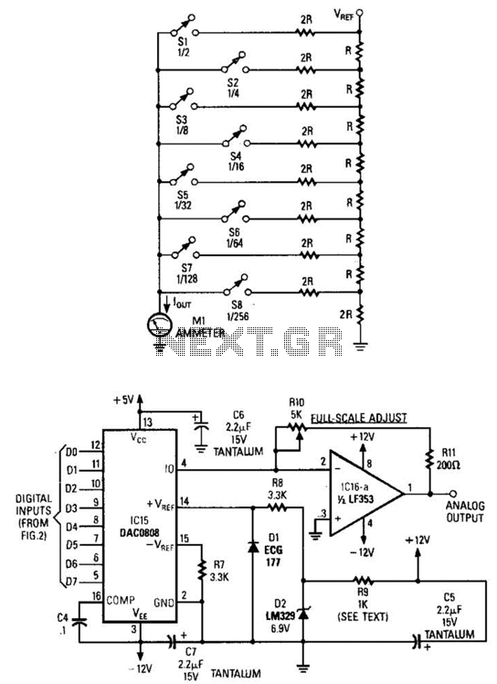
Figure A illustrates an R/2R resistor ladder. Each closed switch increases the current flow. A basic channel A/D converter is depicted in Figure B. The voltage reference (D2) is shared across all channels, although the value of the dropping...
This electronic circuit utilizes a 555 timer as the foundation for a touch switch. When the plate is touched, the 555 timer is activated, causing the output on pin 3 to go high, which turns on the LED and...
This automatic NiCd charger for 9V NiCd batteries utilizes the properties of a 555 timer and is straightforward to construct. The design allows for continuous charging of the battery without the risk of overcharging or discharging. With the specified...
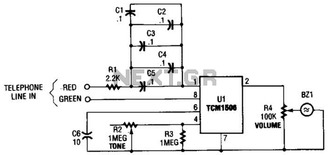
The circuit utilizes the TCM1506 ring detector/driver integrated circuit, which is a monolithic IC designed to replace mechanical bells in telephones. It is powered and activated by the telephone line's ringing signal, which ranges from 40 to 150 V...