
Sealed Lead-Acid Charger

The circuit described utilizes the L200 voltage regulator, which is specifically designed for applications requiring adjustable output voltage and current limiting. The L200 can handle input voltages up to 40V and can output a maximum current of 3A, making it suitable for charging sealed lead-acid batteries.
The circuit should include a transformer to step down the AC mains voltage to a lower level suitable for the L200. A full-wave bridge rectifier is recommended to convert the AC voltage to DC, followed by a smoothing capacitor to reduce ripple voltage. The output from the rectifier should be connected to the input of the L200.
To set the desired output voltage for charging the lead-acid battery, a voltage divider can be used at the feedback pin of the L200. This allows for precise adjustment of the output voltage to match the battery's charging requirements, typically around 13.8V to 14.4V for sealed lead-acid batteries.
Current limiting can be implemented by placing a resistor in series with the load (the battery). The L200 has built-in current limiting features, allowing it to automatically reduce the output current if the battery approaches its maximum charging rate. This protects the battery from overcharging, which can lead to damage or reduced lifespan.
For float charging, the circuit should be designed to switch to a lower voltage once the battery reaches full charge. This can be achieved by using a relay or a transistor that senses the battery voltage and adjusts the output of the L200 accordingly. When the battery is fully charged, the output voltage can be reduced to around 13.2V, which is sufficient to maintain the charge without overcharging.
Finally, it is important to include appropriate heat sinking for the L200, as it may dissipate significant power during operation, especially when charging at higher currents. Adequate thermal management will ensure reliable operation and longevity of the components.
In summary, the charger design leveraging the L200 chip provides a robust solution for charging sealed lead-acid batteries efficiently and safely, while allowing for indefinite connection to the power source without the risk of damage to the battery.Here`s how to make a good charger for a sealed lead-acid battery (this will NOT work with NiCad batteries) that`s faster (because it allows more current into the battery initially) and safer (because it uses lower voltage when the charging is finished). The battery can be left plugged into this charger indefinitely, and it won`t bother it in the slightest.
In fact this is the "float" or "standby" charging method recommended by battery manufacturers. Below is a circuit based around an L200 chip. (Note to US residents: the L200 is more easily available in Eurpore than in the US. I hear that they are available in the US from BG Micro. If BG has run out, you may consider an equivalent made from an LM317 🔗 External reference
Related Circuits
This circuit allows appliances to remain connected to an inverter. While it does not influence weather conditions, it ensures that batteries are safely charged even during periods of generation shortfall. This device is referred to as the Grid Charger...
In a lithium-ion cell, a voltage of 3.8V per cell indicates a state of charge of approximately 50%. It is important to note that using voltage as a fuel gauge is not precise, as cells manufactured by different companies...
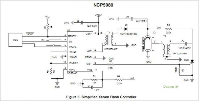
The NCP5810D is a dual-output DC/DC converter capable of generating both positive and negative voltages. This device is optimized for powering modules such as AMOLED display drivers, where high output voltage accuracy, regulation, signal integrity, and compact design are...
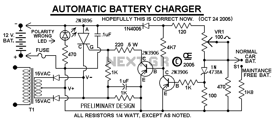
This Charger Can't be used as a Power Supply, Without having a battery in place. The Battery MUST be Connected to get power out. Note: This Charger Features a Reverse polarity Indicator. Instructions: Before plugging this charger into the...
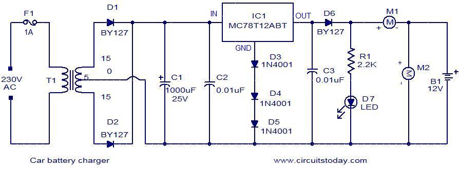
Below is a simple circuit designed for charging car batteries. This circuit includes the capability to monitor both the charging current and voltage. It utilizes the IC MC78T12ABT from Freescale, which is essentially a 7812 in a TO-3 package...
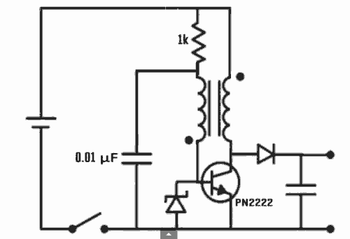
Excellent Joule thief circuit idea! The Joule Thief is a simple yet effective circuit designed to extract usable voltage from low-voltage power sources, such as depleted batteries. This circuit operates on the principle of boosting voltage through the use...