
Car battery charger

The circuit operates by first stepping down the AC mains voltage using transformer T1, which is critical for safe operation. The output from the transformer is then rectified by diodes D1 and D2, converting the AC voltage to DC. This DC voltage is filtered by capacitor C1 to smooth out any ripple, ensuring a stable voltage supply for the rest of the circuit. Capacitor C2 acts as a decoupling capacitor, helping to stabilize the voltage supplied to the IC and preventing fluctuations that could affect performance.
The MC78T12ABT voltage regulator is pivotal in maintaining a consistent output voltage. By elevating the ground terminal to 2.1V with the help of diodes D3, D4, and D5, the output voltage is adjusted to a regulated 14.1V, which is optimal for charging car batteries. This configuration allows for efficient battery charging while providing the necessary safeguards against reverse current flow through diode D6.
The inclusion of meters M1 and M2 enhances the functionality of the circuit by providing real-time monitoring of the charging conditions. Meter M1 displays the charging current, allowing users to assess the charging rate, while meter M2 shows the charging voltage, ensuring that the battery is receiving the correct voltage level throughout the charging process. This circuit is not only straightforward in design but also effective in its application for charging car batteries safely and efficiently.Given below, is a very simple circuit that can be used for charging car batteries. In this circuit there is facility for monitoring the charging current and voltage. The circuit is based on the IC MC78T12ABT from Freescale. The IC is nothing but a 7812 in TO-3 package with 3A capacity. The transformer T1 steps down the mains voltage and diodes D1&D 2 does the job of rectification. Capacitor C1 does the filtering and C2 acts as a decoupling capacitor. The ground terminal of IC1 is lifted to 2. 1V using the diodes D3, D4 and D5. So the output from the IC1 will be a regulated 14. 1V (12+2. 1). The battery is charged via diode D6. The D6 blocks reverse flow of current from battery to charging circuit when the mains power is not available. Meter M1 shows the charging current and M2 shows the charging voltage. 🔗 External reference
Related Circuits
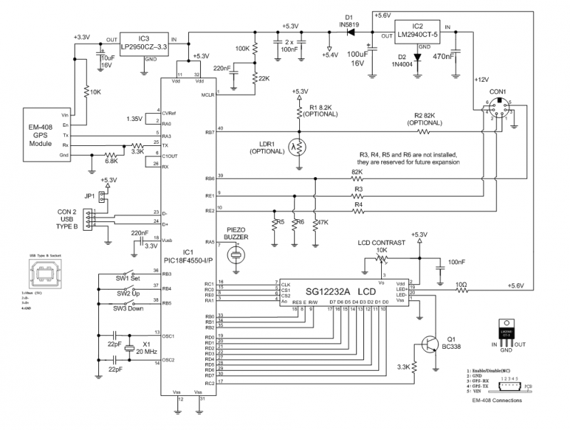
The GPS Car or Boat Computer is capable of displaying a variety of GPS-related information for enthusiasts of driving or boating. This page contains all the necessary information to construct the unit, including design specifications, schematic diagrams, parts list,...
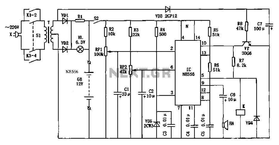
This circuit is a sound generator designed to simulate the siren of a British police car. It utilizes two timer IC 555 components to produce sound frequencies. The operation of the circuit involves the 555 timer on the right,...
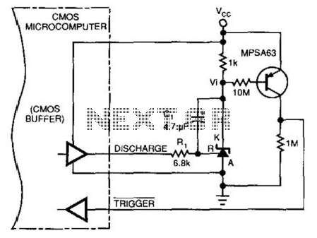
This circuit enables a microprocessor system to measure its own battery voltage. A Texas Instruments TI43 precision shunt regulator functions as a precise reference and integrator/amplifier, measuring its own supply through voltage-dependent charge and discharge time intervals. It is...
As shown in the generator start battery automatic monitor circuit diagram. The generator start battery automatic monitor circuit is designed to oversee the battery's status during generator operation. This circuit ensures that the battery remains charged and functional, preventing premature...
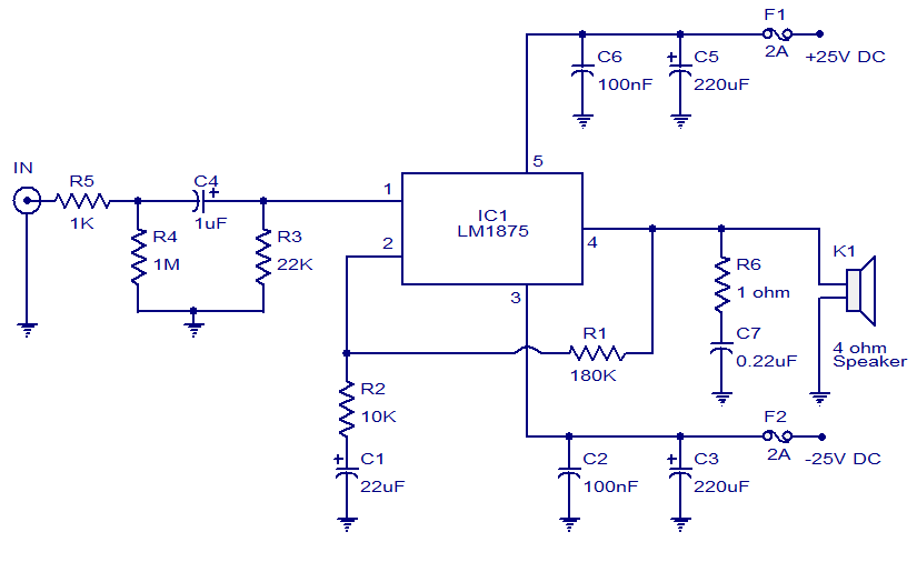
This weblog focuses on electronic circuit schematics, PCB design, DIY kits, and electronic project diagrams. The featured project is a 20W audio amplifier circuit based on the LM1875 audio amplifier IC from National Semiconductors. With a 25V power supply,...
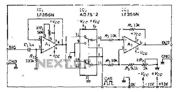
An analog switch (double loop, double-break) and a differential modulation amplifier are used in this circuit. The carrier control switch operates by switching contacts at specific times, inverting the input modulation wave. When the next carrier signal is applied...