
Security Monitor
The circuit design effectively combines a remote microphone preamp and an audio amplifier to facilitate sound monitoring in various environments. The use of an ECM microphone ensures high sensitivity to sound, while the two-stage transistor amplifier enhances the weak microphone signal, optimizing it for further processing. The gain control provided by the preset resistor allows for adjustments based on the environment, accommodating varying sound levels. The capacitors employed throughout the circuit play critical roles in both signal integrity and power supply decoupling, thus ensuring a clean audio output devoid of unwanted noise.
The TL071 operational amplifier is chosen for its low noise and high performance, making it suitable for audio applications. The design considerations for high-frequency roll-off are particularly important in environments where radio frequency interference could degrade audio quality. The LM386 audio amplifier is a robust choice for driving speakers or headphones, with its built-in features allowing for efficient amplification with minimal distortion. The overall circuit is well-suited for applications requiring discreet sound monitoring, providing reliable performance in remote locations.Use this in your garden and listen for any unusual sounds, or maybe just wildlife noises. If you have a car parked in a remote location, the microphone will also pick up any sounds od activity in this area. The cable may be visible or hidden, screened cable is not necessary and you can use bellwire or speaker cable if desired.
Starting from the right hand side, the power supply. I have used 12V as a standard power supply voltage, or a 12V car battery may be used. The circuit is in two halves, a remote microphone preamp, and an audio amplifier based around the National Semiconductor LM386 audio amplifier. The remote preamp uses an ECM microphone to monitor sound. A direct coupled 2 stage amplifier built around Q1 and Q2 amplify the weak microphone signal. Preset resistor R2 acts as a gain control, and C1 provides some high frequency roll off to the overall audio response.
Q1 is run at a low collector current for a high signal to noise ratio, whilst Q2 collector is biased to around half the supply voltage for maximum dynamic range. The power supply for this preamp is fed via R10 and R6 from the 12V supply. C4 ensures that the preamp power supply is decoupled and no ac voltages are present on the power lines.
The amplified audio output from Q2 collector is fed onto the supply lines via C6 a 220u capacitor. The output impedance of Q2 is low, hence the relatively high value of C6. C6 also has a second purpose of letting the output audio signals pass, whilst blocking the dc voltage of the power supply. At the opposite end, C7 a 10u capacitor, brings home the amplified audio to the listening location. The signal is first further amplifier by a x10 voltage gain amplified using the TL071. C8, a 22p capacitor again rolls off some high frequency response above 100kHz. This is necessary as long wires may pick up a little radio interference. After amplification by the op-amp, the audio is finally passed to the LM386 audio amplifier. R14 acts as volume control. R13 and C12 prevent possible instability in the LM386 and are recommended by the manufacturer. Audio output is around 1 watt into an 8 ohm loudspeaker, distortion about 0. 2%. If preferred headphones could be used, although I`d recommend a series resistor of the same value impedance as the headphones.
🔗 External reference
Related Circuits
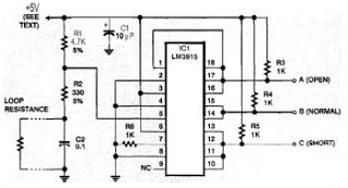
This security system is essential for homes, offices, and factories. It includes a circuit diagram that is simple and easy to construct, making it accessible for anyone. The circuit is cost-effective. Many security systems utilize a closed loop of...
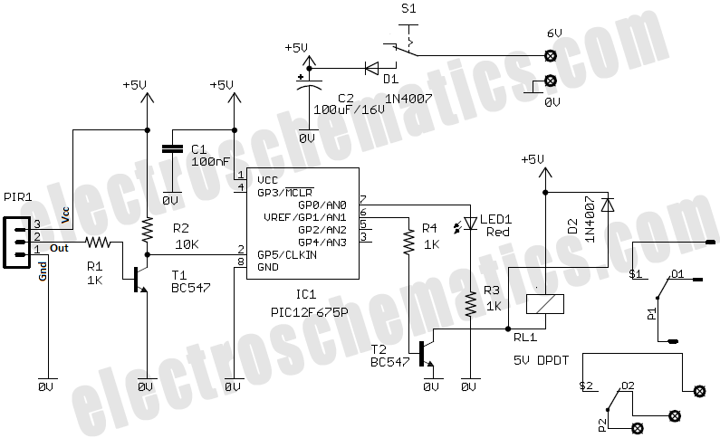
Crime in general is still on the rise, and having a security alarm installed is no longer a prerequisite of the wealthy. Here is a simple and compact security solution. A compact security alarm system can be designed to enhance...
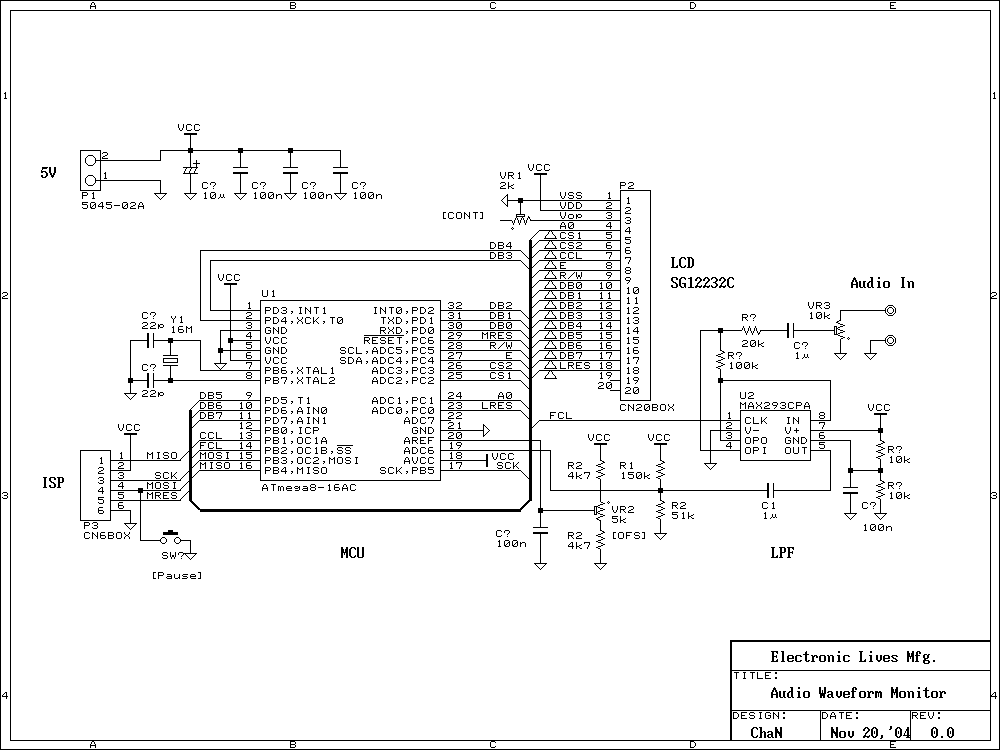
This is an evaluation use of a small graphics LCD module. Last summer, SG12232C graphic LCD module has been sold for 1500 Yens from Akizuki Denshi and I bought it. However, I could not find a good application for...
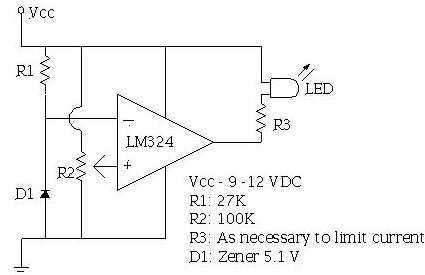
An ECU must have a way to monitor battery voltage. Here is a simple op-amp based circuit which will illuminate the LED when the battery voltage drops to a certain level. The turn-on point is set with R2. You...
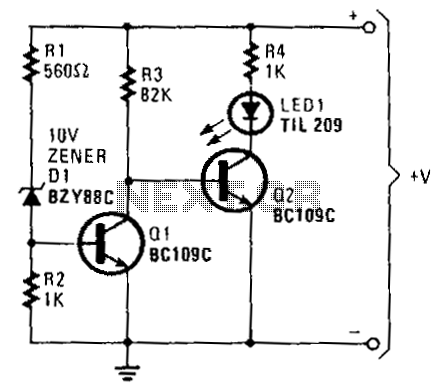
When the battery voltage exceeds approximately 11 V, current flows through resistors R1, D1, and R2. The voltage generated due to the current flowing through R2 is sufficient to turn on transistor Q1, effectively bringing its collector voltage near...
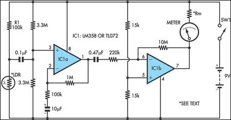
Strictly speaking, this simple circuit should not work. How could anyone expect an ordinary light-dependent resistor (LDR) photocell to detect the change in blood flow as the heart pulsates through a fingertip in natural daylight? The secret lies in...