
safe and security system
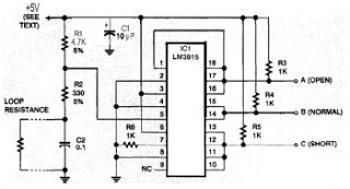
Step 1 involves converting the loop resistance into a voltage, accomplished by integrating it into a voltage divider with resistors R1 and R2. Capacitor C2 serves to protect the circuit from electromagnetic noise, which is crucial since burglar alarms often utilize long wires that run close to heavy electrical equipment. Step 2 translates the voltage into a logic signal to indicate whether it falls within the correct range. The LM3915 is utilized here; although it is designed to drive ten LEDs, it is configured to drive 1K resistors instead. Since the system only needs to identify three conditions rather than ten, some outputs are tied together. The LM3915 features open-collector outputs that can be paralleled in this manner, employing negative logic (0V for "yes," +5V for "no"), which is contrary to standard logic circuits. If positive logic signals are required, inverters such as the 74HC04 can be used. It is important to note that the circuit operates with any supply voltage ranging from 3 to 25 volts; however, if the supply voltage is not 5 volts, the outputs will not be compatible with 5-volt logic circuits.
The design of this security system circuit offers a robust solution to common vulnerabilities associated with conventional alarm systems. The integration of the LM3915 IC allows for precise monitoring of the loop resistance, ensuring that any interruption or tampering is detected reliably. The use of a voltage divider not only facilitates the conversion of resistance to voltage but also enhances the stability of the system against external disturbances, thanks to the inclusion of the capacitor for noise filtering.
Furthermore, the selection of resistors and the configuration of the logic outputs provide a flexible approach to interfacing with various logic levels, accommodating different system requirements. The open-collector design of the LM3915 outputs allows for easy expansion or integration with other components in a larger security system, thus enhancing the versatility of the overall design. This circuit can serve as a foundational element for more complex security applications, providing a balance between simplicity, cost-effectiveness, and reliability.This security system is very important for any kinds of home, office, factor. there has a circuit diagram its simple and easy to build. Any one can do it. It`s a low cost circuit diagram. Many security systems use a closed loop of wires and switches arranged so that whenever a door or window is opened, the loop will be broken and the alarm will sound. An obvious problem is that someone can tamper with the system, short out the loop, and later on, come back and burglarize the premises without sounding the alarm. Hiding a known resistance in the loop, as you propose, is a very good idea. That way, the alarm can distinguish a short circuit from a correctly functioning closed loop. Figure 1 shows a circuit that does the job. It`s a somewhat unusual application of a National Semiconductor LM3915 IC, normally used to drive LED` bar-graph displays.
That chip happens to contain the right combination of comparators and logic circuits to do what you need. Step 1 is to translate the loop resistance into a voltage; that`s done by putting it into a voltage divider with resistors R1 and R2.
Capacitor C2 protects the circuit against electromagnetic noise-important because burglar alarms use long wires, often running near heavy electrical equipment. Step 2 is to translate the voltage into a logic signal indicating whether it`s in resist-he correct range.
That`s where the LM3915 comes in. Normally, the LM3 9 15 would drive ten LED`s, one for each of ten small ranges of voltage. To obtain logic-level outputs, we have it driving 1K resistors instead of LEDs. Since we only need to distinguish three situations, not ten, we tie some of the outputs together. The LM3915 has open-collector outputs that can be paralleled in that way. Note that they use negative logic (OV for yes , +5V for no ), the opposite of ordinary logic circuits. You can use inverters such as the 74HC04 to produce positive logic signals if that`s what you need. Finally, note that the circuit will actually work with any supply voltage from 3 to 25 volts. Of course, if the supply isn`t 5 volts, the outputs will not be compatible with j-volt logic circuits.
🔗 External reference
Related Circuits
.png)
Have you ever considered implementing your own home security alarm system? It is one of the simplest and most interesting circuits for electronics beginners. The new home security equipment utilizes a Light Dependent Resistor (LDR) to detect security breaches....

This is an update to Mr. Hareendran's PIR Sensor Security Light circuit. It has a limitation that restricts the relay voltage to approximately 3.3V. While this may work with some 5V relays, it is not compatible with all. The...
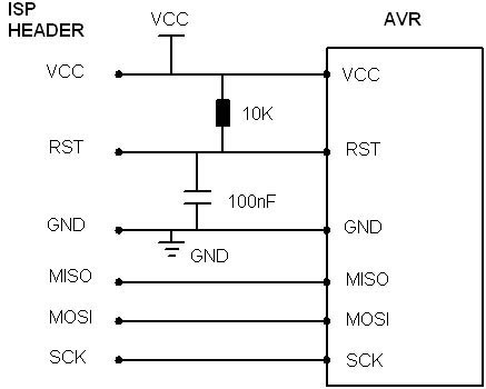
AVR In System Programmer manufactured in the UK by Kanda, a well-known provider of AVR In System Programmers both in the UK and globally. The AVR In System Programmer (ISP) is a specialized device designed for programming AVR microcontrollers directly...
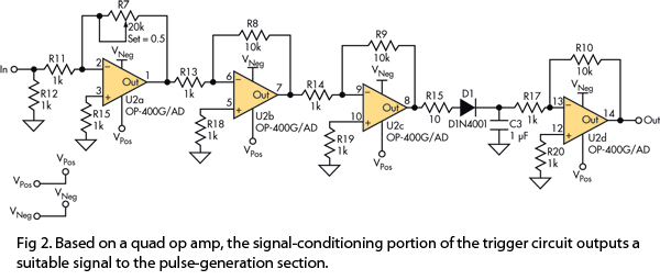
This version of the trigger circuit for the stop-motion camera system utilizes an electret microphone for sonic input, although it can be replaced with an LED and photodiode pair for optical triggering. A recent home-built project involved constructing a...
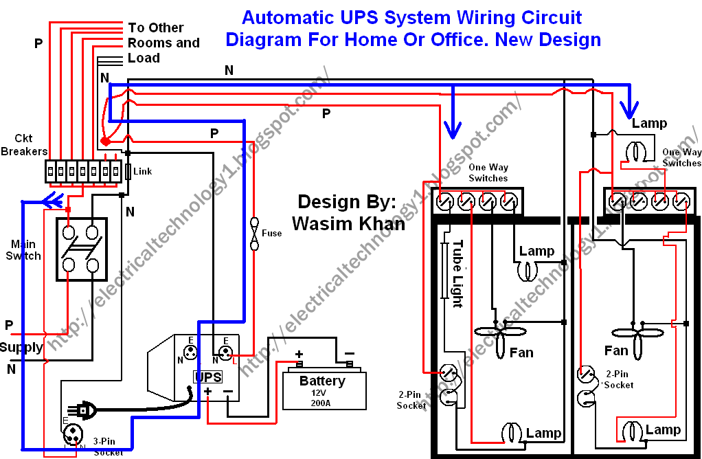
This wiring circuit diagram is designed for providing power to specific rooms in a home or office during a power supply failure. It ensures continuous power supply to devices such as laptops and computers in those particular rooms, especially...

This system utilizes p.A759 audio IC devices and a shared connection between the preamplifiers as an interconnect. Either microphone can drive either speaker. Duplex operation is achievable with a single cable consisting of two wires. The system design incorporates the...