
crystal controlled fm transmitter

The crystal-controlled FM transmitter circuit is designed to generate frequency-modulated signals with high stability and precision. At the core of the circuit is the crystal oscillator, which serves as the frequency-determining element. The crystal's cut and characteristics dictate the operational frequency of the transmitter, ensuring minimal drift and maintaining signal integrity.
The output of the crystal oscillator feeds into the modulation stage, where audio signals are combined with the carrier wave. This modulation can be achieved using a variety of methods, including direct modulation or through the use of a modulator IC. The choice of modulation technique impacts the quality and fidelity of the transmitted audio.
Following the modulation stage, the signal is routed to a series of power amplifier stages. These amplifiers are crucial for boosting the signal strength to a level suitable for transmission over longer distances. Typically, a class A or class C amplifier configuration is employed, depending on the desired efficiency and linearity of the output signal. Careful selection of components, including transistors and passive elements, is essential to optimize performance and minimize distortion.
Additionally, the circuit may include filtering stages to remove unwanted harmonics and ensure compliance with regulatory standards for frequency transmission. Bandpass filters can be used to allow only the desired frequency range to pass through while attenuating out-of-band signals.
For antenna coupling, an impedance matching network is often implemented to maximize power transfer from the transmitter to the antenna. This network ensures that the transmitter operates efficiently and reduces the risk of damage due to reflected power.
Overall, the crystal-controlled FM transmitter circuit is a sophisticated design that balances stability, power, and signal quality, making it suitable for various applications in communication and broadcasting.Circuit of a crystal controlled FM transmitter or crystal transmitter. The circuit is using crystal oscillator and some power amp stages to increase output power. .. 🔗 External reference
Related Circuits
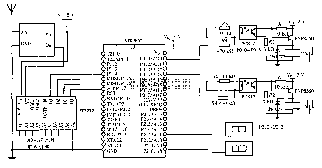
This design aims to create a long-distance wireless remote control switch lighting control system, which consists of a transmission system and a reception system. The system utilizes wireless transceiver modules for RF transmission and reception. The transmitting portion mainly...
Here is the schematic diagram for a very basic crystal radio set without any particular embellishments. This basic old time radio uses no power other than that provided by the transmitting antenna from the radio station. Free power from...
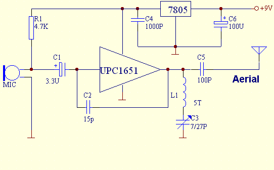
This FM transmitter is built with UPC1651, which is a silicon monolithic integrated circuit specifically designed as a wideband amplifier covering the HF band. The UPC1651 is a versatile integrated circuit that serves as a key component in FM transmitter...
This MP3 player FM transmitter allows users to enjoy their music throughout their home. The transmitter circuit does not require any coils to be wound. When utilized in a vehicle, there is no need for a separate input to...
This circuit is designed for precise centigrade temperature measurement. It features a transmitter section that converts the sensor's output voltage, which is proportional to the measured temperature, into frequency. The output frequency bursts are transmitted through the mains supply...
This circuit generates an FM modulated signal with an output power of approximately 500 mW. The microphone preamplifier is constructed using two 2N3904 transistors, with audio gain controlled by a 5 kΩ preset resistor. The oscillator is a Colpitts...