
Self Powered Sine Wave to Square Converter

The circuit leverages the characteristics of the 4069 IC, which is a hex inverter. Each inverter within the IC can be used to transform the input sine wave into a square wave through its inherent switching behavior. The circuit typically employs a sine wave input, which can be sourced from an audio signal generator or similar device.
To implement this conversion, the sine wave is fed into one of the inverter inputs. The inverter operates by outputting a high signal when the input signal exceeds a certain threshold and a low signal when it falls below that threshold. This results in the generation of a square wave that matches the frequency of the input sine wave but with a distinct waveform.
The absence of a power source in this configuration may suggest the use of passive components such as capacitors and resistors to bias the inverter and set the appropriate thresholds. This could be achieved by connecting the inverter in a configuration that allows it to operate from the input signal itself, possibly utilizing a capacitor to couple the input signal and resistors to set the appropriate gain and biasing levels.
In practical applications, this circuit is beneficial for audio testing, enabling quick checks of audio frequencies and waveform integrity. It offers simplicity and efficiency, making it an excellent choice for engineers and technicians working in audio electronics.Only with a single chip active component (4069 IC), this circuit will convert sine to square waves without a power-source. To test some audio instruments, we.. 🔗 External reference
Related Circuits
The objective is to enhance information transmission by utilizing articles. Please contact us via email at [email protected] within 15 days if there are any issues related to article content, copyright, or other concerns. The articles will be removed promptly. To...

For those who cannot afford the high cost of some SDR radios, there is an alternative. This document describes an intermediate frequency (I.F.) converter suitable for use with Boat Anchor communications receivers. It is now possible to connect the...
One 1381 part (CMOS voltage-controlled trigger available at different limits) should be selected to match the voltage across the motor (2V in this case). The other terminal of the motor is connected to a 3300µF capacitor, which is in...
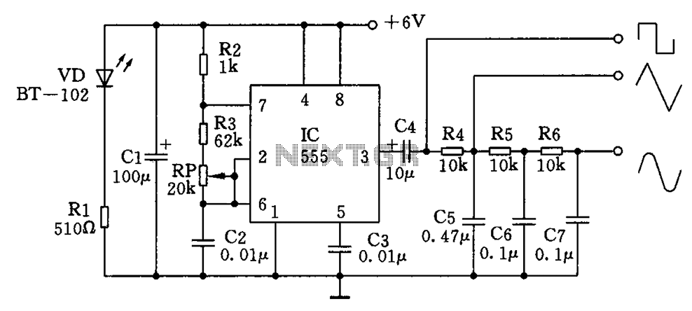
The circuit simultaneously generates a square wave, triangle wave, and sine wave, making it particularly suitable for electronics enthusiasts and students who wish to observe signal waveforms using an oscilloscope. This signal generator circuit is simple, low-cost, and allows...
This high voltage converter circuit begins with a 30-volt power supply and is capable of delivering output voltages ranging from 0 to 3 kV for version 1, or from 0 to 10 kV for version 2. The high voltage converter...
The VFC62 is a voltage-to-frequency and frequency-to-voltage converter that effectively transforms analog signals into digital signals. The digital output is presented in an open collector format, where the digital pulse repetition rate is directly proportional to the amplitude of...