
Photoelectric Sensor Circuit

The described circuit operates as a non-contact intrusion detection system utilizing a light-dependent resistor (LDR) for light sensing. The LDR (R5) plays a critical role in the functionality of the circuit. When exposed to sufficient light, the resistance of R5 decreases significantly, allowing current to flow to the base of Q1, a general-purpose NPN transistor. This transistor, when activated, conducts and pulls its collector voltage close to ground, thus affecting the operation of the subsequent transistor, Q2.
Transistor Q2, a 2N3906 PNP type, is configured in such a way that it acts as a switch for powering the alarm circuit. When Q1 is in saturation, it effectively pulls the base of Q2 low, turning it on. In this state, the collector of Q2 is connected to the positive supply voltage, allowing current to flow through the alarm system, which may include a buzzer or a siren, thus notifying of the intrusion.
The circuit's design allows for a high degree of sensitivity and reliability in detecting intrusions. The use of an LDR provides a simple yet effective means of detecting changes in light levels, which is crucial for the operation of the alarm system. The transition from a closed to an open circuit state upon interruption of the light path ensures that the system can promptly respond to unauthorized access attempts, making it suitable for various security applications.
Overall, the integration of the LDR with the transistor switching mechanism forms a robust detection system that can be easily implemented in a variety of security setups, offering an effective solution for intruder detection without the need for physical contact. The circuit can be used as a sensor that can trigger an alarm, without direct contact being made by the intruder. In this circuit, a visible or invisible light source radiates on the sensor, keeping the detection loop in what could essentially be called a normally closed condition.
As long as the light source striking R5 remains uninterrupted, the switch remains closed. But if an intruder passes between the light source and the sensor, the circuit goes from closed to open, and triggers the alarm. A light-dependent resistor (LDR), whose resistance varies inversely in with the amount of light hitting its sensitive surface, is used.
A bright light aimed at R5 causes its internal resistance to drop as low as a few hundred ohms; in total darkness, the unit`s resistance can rise to several megohms. The light-dependent resistor (R5) is connected between the +Vsupply and the base of Ql. As long as R5 detects light, it supplies ample base current to cause Ql`s collector to saturate to near ground level.
That also pulls the base of Q2 (a 2N3906 general-purpose pnp transistor) to near ground level, turning it on and clamping its collector to the + V rail. 🔗 External reference
Related Circuits

The DTMF decoder can be powered by a 9V battery or through a parallel printer port. It is capable of detecting and displaying all 16 DTMF digits on a computer screen in real-time. The accompanying Windows program can run...

The DC current negative feedback BTL circuit illustrated in Figure 2 eliminates the standard BTL circuit capacitors C12 and C22, which affects the DC characteristics of the circuit. Resistors R16 and R26 function as sampling resistors, while R15, R16,...
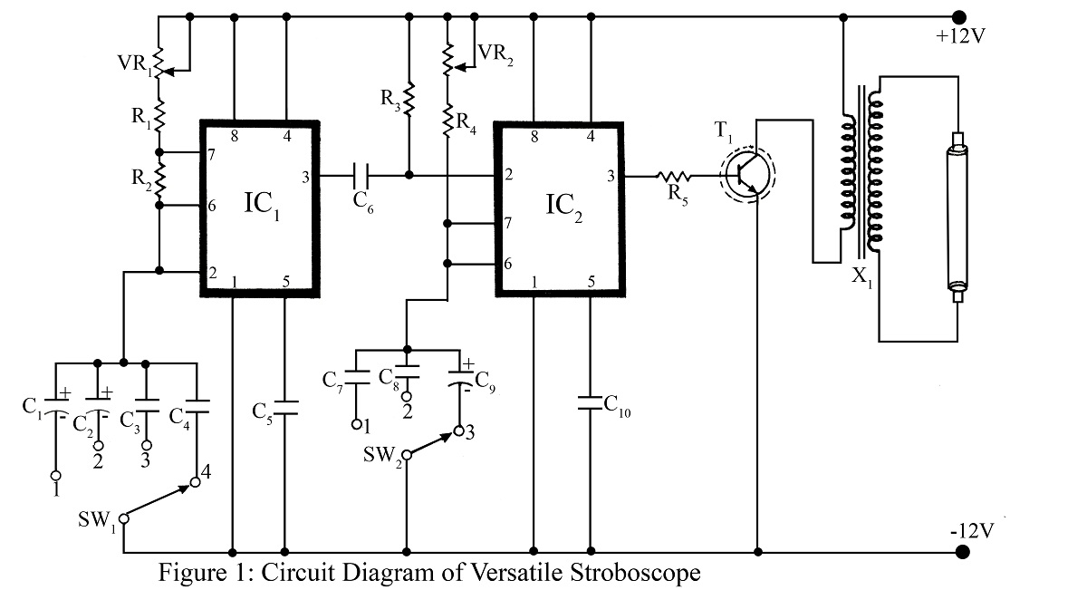
A stroboscope is an instrument used to observe rapidly moving objects with periodic motion as if they are stationary. The strobe light flashes at a frequency that synchronizes with the rotation of a wheel or moving object, creating the...

The transmitter for the wireless headphones is constructed using a CD4046 CMOS phase-locked loop, which is paired with a driver transistor and a set of infrared LEDs. While the CD4046 contains two phase comparators, a voltage-controlled oscillator (VCO), a...

The PIC16F84A digital thermometer circuit is constructed primarily using a temperature sensor along with various discrete components. The PIC16F84A microcontroller serves as the core processing unit of the digital thermometer circuit. It is equipped with an 8-bit architecture and supports...

This is a design circuit for a soft light dimmer. The circuit utilizes the IGBT STGP10N50A and the TS555 timer as the main components. The timer is triggered by the zero crossing voltage pulse. The time constant, determined by...