
soft light dimmer circuit

The soft light dimmer circuit is an efficient solution for controlling the brightness of lighting fixtures using a combination of an Insulated Gate Bipolar Transistor (IGBT) and a timer IC. The primary component, the IGBT STGP10N50A, is selected for its ability to handle high voltages and currents, making it suitable for dimming applications. The TS555 timer is configured to operate in a mode that allows it to trigger the IGBT based on the zero crossing of the AC voltage, which minimizes electromagnetic interference and provides a smoother dimming experience.
The time constant, defined by the capacitor C5 and the resistors R14 and R15, is crucial as it determines the conduction angle of the IGBT. By adjusting these components, the dimming range can be fine-tuned to meet specific requirements. The circuit also incorporates T2 and T3, which serve as control elements to inhibit the power switch until the auxiliary supply voltage reaches a minimum threshold of 8V. This feature ensures that the IGBT gate receives a sufficient voltage level for reliable operation.
The inclusion of R5 as a current sense resistor is essential for providing protection against short circuits and over-current conditions. When the current flowing through R5 exceeds a predetermined level, the voltage across R5 will trigger the gate of the sensitive gate thyristor, causing the IGBT to turn off. This action not only protects the circuit from damage but also resets the timer, preventing further triggering until conditions are safe.
Furthermore, the current limiting feature is instrumental in managing excessive inrush currents that can occur during the initial power-up phase of the circuit. By implementing this design, the circuit achieves an automatic soft-start capability, which gradually ramps up the current, thereby reducing stress on both the IGBT and the connected load. Overall, this soft light dimmer circuit is a robust solution for controlling lighting with enhanced safety and performance.This is a design circuit for soft light dimmer. This circuit uses the IGBT STGP10N50A and the TS555 timer as main components. The timer is triggered on the zero crossing voltage pulse. The time constant determined by C5/R14+R15 that is used to determine the conduction angle. The T2 T3 inhibits the power switch until the auxiliary supply voltag e reaches 8V to guarantee that the gate of the IGBT receives correct voltage level. This is the figure of the circuit R5 is the current sense resistor, that is used for the short circuit and over-current protection. The gate of the IGBT will taken low and turn off, when the voltage across R5 reaches the sensitive gate thyristor`s gate trigger voltage.
At the same time the timer will reset. This current limiting also provides protection against excessive in-rush current and automatic soft-start. [Circuit Source: STMicroelectronics Application Note] 🔗 External reference
Related Circuits

This circuit is designed to detect clipping in a specific waveform. Clipping occurs when the amplitude of a waveform decreases before reaching its expected limit. The circuit activates an LED as an indication that the tested signal is experiencing...
This circuit is a simple manual analog light control desk that outputs standard 0-10V control signals suitable for controlling professional light dimmers and other lighting equipment. The controller's output is a steady DC voltage that varies between 0 and...
Connect a 12-volt, 20-watt lamp and a 12-volt battery to the circuit, ensuring correct battery polarity. Momentarily pressing and releasing the button will turn the lamp on. Repeatedly pressing the button will cycle through different power levels. Pressing and...
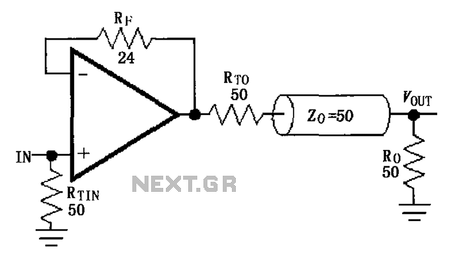
The MAX4450/4451 unity gain line is illustrated in the driving circuit. The MAX4450/4451 features internal compensation, a 24-ohm resistor in series within a feedback loop, along with capacitors and inductors that can reduce the Q value of the feedback...
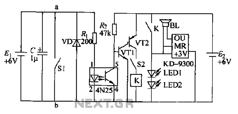
Due to the fast pace of modern life, intense competition, and widespread insomnia, which poses health risks, this section presents a feasible and effective method for controlling photoelectric hypnotic music to alleviate insomnia and facilitate sleep. The principle circuit...
A well-designed circuit that automatically turns off if the pushbutton is held down or jammed for an extended period. It is not re-triggerable while the light remains on. The circuit initially starts at full brightness and gradually dims to...