
Plant-Pot Water Level Indicator Circuit
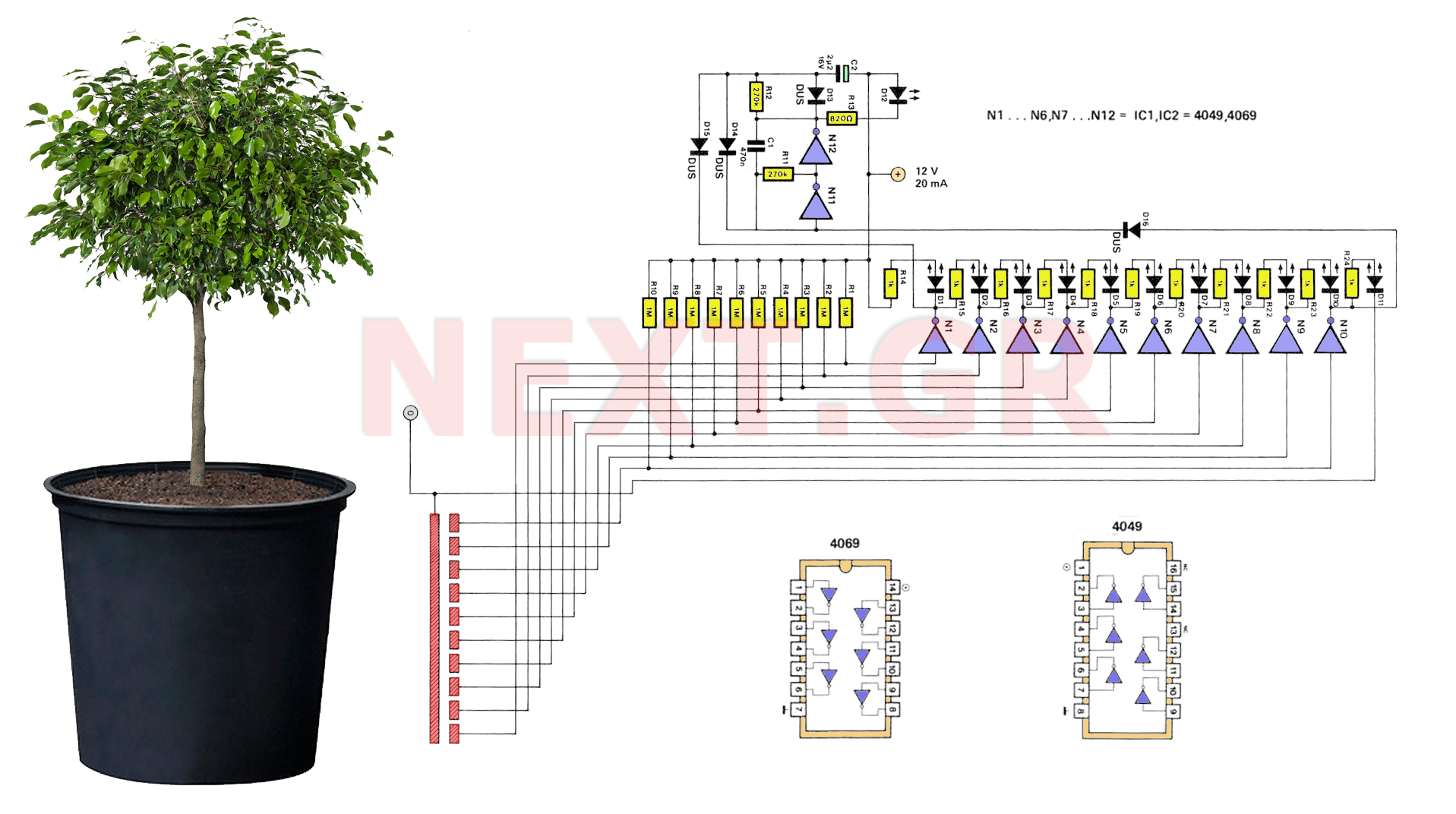
When the water level decreases to the point where the area between the electrodes, soil, and the electrode connected to the N10 input dries out, the input to N10 through resistor R10 becomes HIGH. This causes the output of N10 to switch to LOW, turning off LED D11. Meanwhile, LEDs D1 to D9 remain off, while D10 illuminates due to the LOW output from N10 and the HIGH input from N9 through resistor R23. The operation continues such that whenever the water level falls below a specific threshold (i.e., contact point), the corresponding LED diode activates, facilitating easy detection of soil moisture. If the dryness in the soil increases to the point where it affects the last electrode (towards N1), the final LED in the series (D1) will illuminate, triggering the unstable multivibrator formed by N11 and N12. This causes LED D12 to start flashing, signaling an urgent need for watering. Since D16 is connected to the output of N10, D12 will continue to blink until the water level rises to the corresponding threshold of N10.
The design does not include a ready-made PCB image; however, creating a suitable printed circuit board is relatively straightforward, allowing most individuals to design one independently. The appropriate length of the moisture detection section and the spacing between successive sections will depend on the dimensions and shape of the pot being used.
The circuit primarily consists of a moisture sensing mechanism using copper contacts that function as electrodes. When the soil is adequately moist, the contacts are submerged, providing a LOW signal to the inverters. The inverters are configured to output a HIGH signal when the corresponding inputs are LOW, which keeps the primary alert LED (D11) illuminated. As the moisture level decreases, the circuit transitions, activating other LEDs based on the moisture level detected by the contacts. The design allows for a tiered alert system, where multiple LEDs indicate varying levels of moisture, ensuring that the gardener is informed of the specific needs of the plants. The flashing LED (D12) serves as a critical warning for immediate action, emphasizing the device's role in effective plant care. The overall layout and connections should be carefully planned to ensure reliability and ease of use in various gardening scenarios.A series of LEDs serve to alert the gardener when plants need water. Using two conventional digital integrated LEDs and a series of LEDs, we make a very useful device for gardening. The device detects the amount of water in the pot and alerts the grower. The circuit of the device is shown in Figure 2. The water detection is made from the bottom of the circuit in the form of ten copper contacts - inputs to the inverters N1 - N10.
These inputs are LOW, about 0 volts, that is, when they are covered with water. Correspondingly, the inverter outputs are HIGH, they are positive. In this situation, the LED diodes D1-D10, as they are connected. Are without potential difference and therefore do not flicker. Only the D11 lights up because its uplink is connected to the N10 output (HIGI) via R24 while its cathode is permanently at 0 volts. Turning on D11 means that the pot has a good amount of water (or moisture).
When the water level decreases so as to dry the portion between electrode, earth and electrode connected to the N10 input, the input of N10 through R10 will become HIGH. So the output of N10 will become LOW. The LED D11 stops being switched off and extinguished. D1 - D9 remain unaffected, ie off. But the D10 lights up. Because its descent is LOW by the output of N10 and the rise of HGH through R23 and the output of N9.
From now on, the operation is simple.
Whenever the water level drops below a graduation (ie contact) of the device, the corresponding LED diode turns on. Thus, water in the soil is easily detected. If the drought in the land on which the pointer is pulled is increased so that it stops and the last road (towards the N1), the last LED of the series (D1) will turn on and then the diode system D13 to D16 will activate the unstable multiplier Formed by N11 and N12.
The LED D12 will now start flashing, indicating the immediate need for watering. Since D16 is connected to the N10 output, D12 will continue to blink until the water level rises to the N10-corresponding field.
Unfortunately, there is no ready PCB image but it is not difficult, so most could design a proper printed circuit on their own. Of course, the correct length of the moisture detection section and the distance between successive sections will depend on the size and shape of your pot.
Related Circuits
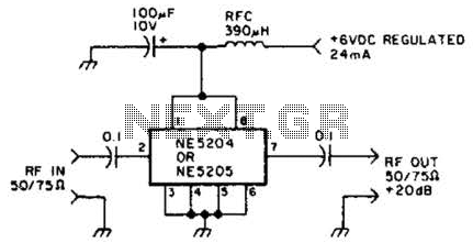
The Signetics NE5204 or NE5205 can be utilized in this audio frequency to 350-MHz (-30 dB) preamplifier. For a requirement of 600 MHz at 3 dB, the NE5205 should be employed. The noise figure is 4.8 dB at 75...
The circuit for the ball game scoring device is depicted in the accompanying image. This device records and displays the performance of a ball game. The first Nixie tube has two states: it can either be off or display...
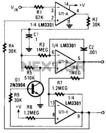
The Phase-Locked Loop (PLL) will synchronize with an input signal, providing both triangle and square wave outputs. A quad operational amplifier can be utilized in this circuit, making it suitable for audio and low-frequency radio applications. The Phase-Locked Loop (PLL)...
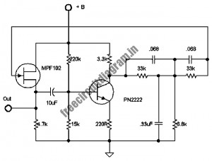
The following circuit illustrates a stable 60 Hz frequency signal generator circuit diagram. Features include a 0.068 µF capacitor incorporated within a feedback loop, allowing for DC-to-AC conversion. This circuit is designed to generate a stable 60 Hz sine wave...
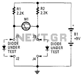
This circuit can be utilized to match diodes for applications where balance is essential, such as in a balanced modulator. The diode matching circuit will display the forward voltage drop of the two diodes in millivolts. The diode matching circuit...
The LM1036 is a DC-controlled circuit designed for tone (bass/treble), volume, and balance adjustments in stereo applications, including car radios, televisions, and audio systems. It features an additional control input for easy loudness compensation. The circuit includes four control...